Stay Informed
Follow us on social media accounts to stay up to date with REHVA actualities


This paper regards to basic indoor environmental parameters in administrative spaces of two office buildings in Bratislava, Slovakia in summer and in winter period.
A large number of people often experience discomfort due to draught, low or high temperatures when they are at work. Office buildings with facades made in high extent of glass are influenced by outdoor conditions. Therefore it is necessary to equip them with some of the systems of building services in order to ensure optimal indoor conditions. One of such systems is the low-exergy system, what means low temperature heating and high temperature cooling in one system. This system is one of types of radiant surface heating and cooling and consists of radiant heating and cooling panel systems with integrated pipes suspended under the ceiling or embedded id building construction. Thermal energy is exchanged between the room and people present in the space and the heated / cooled surface.
The office building is located in Bratislava, Slovakia. It is a new administrative building (Figure 1), built in 2008. The building has two underground floors and 8 floors above the ground. The Office building has a completely glass facade.
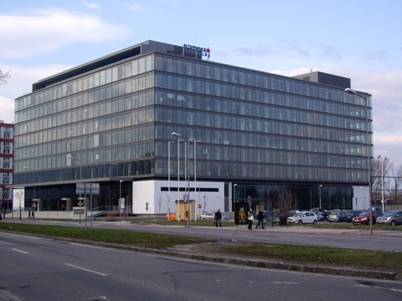
Figure 1.Office building.
![]() In the administration part the fresh air is supplied to office
spaces by means of under floor air distribution system. Radiant heating and
cooling panel systems with integrated pipes suspended under the ceiling are
installed (Figure 2). Thermal energy is exchanged between the
room and people present in the space and the heated / cooled surface.
In the administration part the fresh air is supplied to office
spaces by means of under floor air distribution system. Radiant heating and
cooling panel systems with integrated pipes suspended under the ceiling are
installed (Figure 2). Thermal energy is exchanged between the
room and people present in the space and the heated / cooled surface.
The radiant heating/cooling panels are with pipes Ø 8 mm and 12 mm, made of copper.
Radiant ceiling are installed by means of a hangers in order to fix the pipes, which are made by copper. The ceiling is composed by: insulation, hangers, pipes, wire net, plaster. These ceiling panels are usually used for open space offices like here. The maximum surface temperature depends on the criteria for radiant asymmetry or direct contact with the surface [2]. Suspended, radiant ceiling systems cover the whole ceiling surface. The insulation over the panel is used to avoid the heat losses to the construction above. [1].
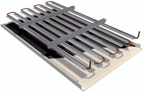
Figure 2. Radiant heating/cooling panel [11]
The second building was built in 2009 and has two separate blocks: block A (5 floors) and block B (8 floors).
There is applied system of capillary pipes embedded in a layer at the inner ceiling surface (Type F).
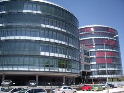
Figure 3.Building B.
Cooling grids made of small plastic tubes of 5 mm in diameter placed close to each other can be embedded in additional plaster or gypsum board attached to the slab. The heat transfer from the room above is higher than in the case of cooling panels. The heat transfer to the concrete slab couples the cooling grid to the structural thermal storage of the slab, thus the building structure is secondarily activated. It means that the system is faster in response than TABS, because the smaller part of the slab is deeply activated.
Adding a layer of insulation below the floor reduces the cooling the floor of the room above [1].
Figure 4. TABS “F” with an without acoustic insulation: 1 = Floor surface covering, 2 = Screed material, 3 = Acoustic insulation, 4 = Building structure, 5 = Plastic micro pipes, 6 = plaster or gypsum [1].
The purpose is to provide a healthy and comfortable indoor environment, which enhances the performance of the occupants at low energy consumption.
A dominant assumption in the design of many modern buildings is that indoor environmental parameters can and must by carefully controlled within the limits established in the prevalent codes, standards (EN 15251) and guidelines [1].
In indoor environment four major factors are evaluated:
· Thermal environment
· Air quality
· Acoustics
· Lighting
These four factors are usually dealt with individuality. Actually, they are all closely coupled and determine the effects of the building on the occupants [13].
The aim of this study is thermal comfort.
The environmental parameters of temperature, thermal radiation, humidity and speed of air velocity necessary for thermal comfort depend upon the occupant clothing and activity. The thermal environment is acceptable, if is satisfaction with them 80% of the occupants. The individuals who feel general thermal discomfort also feel local thermal discomfort, therefore the percentages of dissatisfied are not additive. It is assumed than 20% will be dissatisfied when the recommendations of the standard AHSRAE 55 are followed [13].
Indoor environmental parameters, which directly affecting the heat balance of human body and directly related to the thermal comfort:
· Insulation of clothing
· Metabolic rate
· Air temperature
· Mean radiant temperature
· Relative air velocity
·
Relative humidity
Evaluation of the indoor environment is based on time and space temperature distribution in the room. Measuring positions and devices must comply with requirements according to CEN CR 7726. Measurements of indoor environment parameters are necessary for evaluation of thermal environment at working places and its influence on people and their performance. Thermal environment is evaluated according to thermal conditions in winter – recommended values of indoor environment during heating period (EN 15 251). Sampling points were located in corner offices and in the middle of the disposition, and there were compared with each other.
Two types of measurements were performed:
Long-term
measurements were performed with device HOBO logger to obtain the following
parameters in office building:
· Indoor air temperature in °C;
· Relative humidity in %;
The
measurements in both buildings were done during 7 days (according weekend) in
winter period (January) on the typical floor and on the last floor.
Short-term measurements were done by B&K 1213 indoor climate analyzer with sensors. The following parameters were measured at selected working places to find out potential discomfort due to vertical air temperature difference:
· Operative temperature in °C
· Relative humidity in %
· Indoor air velocity in m/s
Operative temperature was measured with an ellipsoid, whose projected area represents the shape of human body. The settlement of measuring device takes 25 minutes before measurement. Measurements were performed at the workplace 0.6 m above the floor. The load on a person is an aggregate of thermal conditions, activities and clothing.
The measurements of the relative humidity were performed with dew-point transducer in height of 0.6 m above the floor at workplace, measurements of the air velocity were done with transducer 0.1 m above the floor – in the area of human ankles, and 1.1 m above the floor at workplace– in the area of the seated person’s head.
Short-term measurements were done on the same days as long-term measurements, in winter conditions, in the same offices, on the typical floors, and on the last floors. Measurements were done on sitting (working) places and on standing places (corridor in the office). Measurement points in the corner were situated in the most critical working place; other points were located in the middle of the disposition.
In Figures 5 and 6 is comparison of air temperature behaviour within 2 working days in building A and B.
The minimum room temperature is in the morning (22°C). Then the heat gains from occupants, equipment and the solar radiation from the outside push the air temperatures up (mainly in corner offices – blue line) (25–26°C).
The heat gains are removed and the room temperature falls down to the necessary starting point after occupants leave the offices. The average air temperatures in most of the offices are around 24°C, which respond to II. category of the standard EN 15 251.
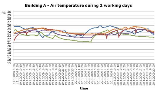
Figure 5. Long-term measurements - air temperature in 2 working days – Building A.
In building B is behaviour of the air temperature very similar to building A. The average temperature during working time is 24 °C, which respond to category II of the standard EN 15 251 as well.
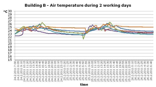
Figure 6. Long-term measurements - air temperature in 2 working days – Building B.
Results of short-term measurement of operative temperature are in Figures 7 and 8. There is a percentage of working places in frame of operative temperature according to EN 15 251 for category III. In some offices is temperature a little bit above this range, but this offices are in the corner and in the time of measurements were there sunny shine.
Figure 7.sort-term measurements - operative temperature – Building A.
Operative temperatures in building B with capillary pipes are in most of the offices around 23°C. On some places was the temperature higher, because of the sunshine during the measurement.
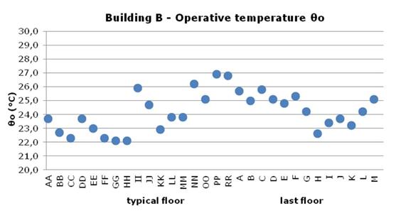
Figure 8. Sort-term measurements - operative temperature – Building B.
Relative humidity in building A with suspended heating panels is between 30 and 40%, which is in the range of requirements of CR 1752.
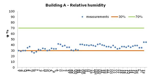
Figure 9.Sort-term measurements – relative humidity – Building A.
Figure 10 shows that the relative humidity in building B is on the lowest limit, 20 to 30%. The reason for this is dehydrating of indoor air per consequences of heating in heating season. It may be appropriate to control the humidity in the mechanical ventilation system.
Too low humidity may cause compliance, especially if would the air humidity of indoor air decrease below 20%.
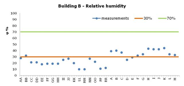
Figure 10.Sort-term measurements – relative humidity – Building B.
Figures 11 and 12 shows the results of short-term measurements of air velocity in occupied zone (on working places) on the last floor. The average air velocity varied between 0.05 to 0.08 m/s, which agree with A category of CR 1752 Ventilation for buildings. The different between height of occupants head and ankles are I average 0.05 m/s. A little bit higher is the value on the working places near the corridor, but still in range of the requirements and without significant risk of draught.
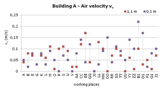
Figure 11. Sort-term measurements – air velocity – Building A.
The situation in the building B are similar as in building A, the average of air velocity is between 0.05 to 0.1, which come under category A of CR 1752, the differences between head and ankles are 0.05 m/s and there is no significant risk of draught.
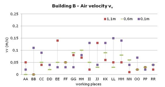
Figure 12. Sort-term measurements – air velocity – Building B.
Most of the parameters of indoor climate are on good level according to international standards EN 15 251 and CEN CR 1752 during winter season. This means, that using low-exergy system seems to be a good choice for buildings with glass facade, where it is more difficult to ensure good indoor environment conditions. Because of the good indoor environment quality, people can feel comfortable, which may have positive influence on their performance. For this type of system correct operation is very important, because of the relatively long time reaction of indoor environment parameters on the operation changes, especially in transition periods.
[1] Olesen B., Petráš D., Babiak J. Low temperature heating and high temperature cooling: REHVA Guidebook No.7: REHVA 2007, ISBN 2-9600468-6-2.
[2] CEN CR 1752 Ventilation for buildings – Design criteria for the indoor environment.
[3] Petráš, D. et al. 1988. Methodics of thermal state evaluation of residential and civic buildings, Civil engineering year-book 1988. Bratislava: Alfa.
[4] Ďurišová E., Petráš D. 2010. Evaluation of indoor environment in office building with low temperature heating and high temperature cooling system in summertime, Clima 2010.Sustainable energy use in Buildings : 10th REHVA World Congress.Antalya,Türkiye,9. 12.5.2010.
[5] Ďurišová E., Petráš D., Krajčík M. 2010. Thermal comfort in the office building with low temperature heating / high temperature cooling and is influence on the quality of the working environment, Healthy buildings 2009: 9th International conference.Syracuse,USA,13. 17.9.2009.
[6] Ďurišová E., Petráš D. 2011. Evaluation of indoor air in office building in Bratislava - in summer and also in winter period, Indoor Air 2011. Austin, Texas, USA, 5. 10.6.2011.
[7] EN 15 377 Design of embedded water based surface heating and cooling systems.
[8] EN 1264 Water based surface embedded heating and cooling systems.
[9] EN 15251 Indoor environmental input parameters for design and assessment of energy performance of buildings-addressing indoor air quality, thermal environment, lighting and acoustics 2006.
[10] EN ISO 7726:1998 Ergonomics of the thermal environment -- Instruments for measuring physical quantities.
[11] www.zent-frenger.de
[12] Indoor Environment and Health, National Institute of Public health, Sweden, 1999, ISBN 91-7257-025-3.
[13] ASHRAE 55 – 1992, Thermal Environmental Conditions for Human Occupancy.
Follow us on social media accounts to stay up to date with REHVA actualities
0