Stay Informed
Follow us on social media accounts to stay up to date with REHVA actualities

With the
transition towards energy supply which has to be based more and more on energy
efficiency and CO2 reduction the decentralized energy systems will
play an important role now and in the future. In general the combined heat and
power (CHP) technology is a well-known and established engineering solution for
energy efficient energy supply. But it is new that the market is getting ready
now also for small-sized CHP units for one- or two-family houses as it was
presented at this year´s ISH in Frankfurt/Germany for
example under the topic of Micro-CHP appliances. This article describes these
appliances only for the three different technologies “Stirling
Engine”, “Internal Combustion Engine” and “Fuel Cell” with the help of some
product examples.
The ViessmannVitotwin 300-W (Figure 1) is an example for a Micro-CHP appliance with a Stirling
engine (Figure 2) which is hermetically sealed and
almost maintenance-free. It runs quietly and therefore it allows an installation
close to the living space.
The gas
fired stirling engine
generates 6 kW heat with an efficiency of 81% (gross cv)
and 1 kW power with an efficiency of 15% (gross cv)
simultaneously. The integrated gas fired peak load boiler of the Vitotwin 300-W can generate heat between 6 kW and 20 kW
in addition with 98% efficiency (gross cv).
Therefore this high-efficient Micro-CHP is suitable for old and new detached
houses and also for two-family houses. With an annual consumption of gas of 26 000 kWh
or more and power consumption above 3 000 kWh per year the Micro-CHP
works with exceptional economy.
The stirling engine operates in a
heat-led mode. The constantly generated power of 1 kW covers the base load
of the electricity demand on site and surplus power is exported to the public
grid, which is remunerated.
Due to the
daily fluctuation of the heat consumption on the one hand and the constantly
generated heat during the operation of the Micro-CHP on the other hand the combination with a heating water buffer
cylinder is essential (Figure 3).
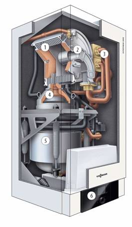
1 - ViesmannInox-Radial heat exchanger
η= 96%
2 - MatriX cylinder burner, Modulation range 4.5–20 kW, Nox <40 mg/kWh, CO <50 mg/kWh
3 - Air distribution valve
4 - Stirling burner
5 - Stirling engine, Performance = 1 kWel,
Maintenance-free
6 - Control
Figure 1.
Wall mounted ViessmannVitotwin
300-W Micro-CHP appliance with a Stirling engine
(lower half) and with integral peak load boiler (upper half). Image source: www.Viessmann.com
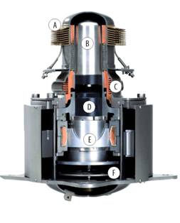
A - Hot area, B - Displacer piston, C - Cold area, D - Working piston, E - Power generation, F - Cylinder retriever
Figure 2.
Hermetically sealed Stirling engine with the
heating-up heat exchanger and the displacer in the upper part, water-cooled
heat exchanger in the middle part and power piston, springs, coil and magnets (Linear Generator for electrical
output) in the lower part. The displacer moves helium from the heated area to
the cooled area. The alternately heated and cooled helium expands and contracts
what creates pressure waves and that then again let the working piston move.
The working piston is a part of the linear generator which produces electricity
while the working piston is moving. Image source: www.Viessmann.com
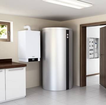
Figure 3.ViessmannVitotwin 300-W Micro-CHP appliance with a heating water buffer
cylinder. Image source: www.Viessmann.com
The VaillantecoPOWER 1.0 is an
example of a Micro-CHP appliance with an internal combustion engine (Figure 6).
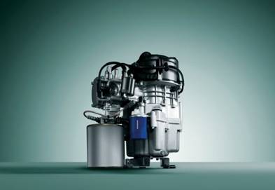
Figure 4.
Gas-Internal Combustion Engine (single-cylinder four-stroke piston engine).
Electrical output 1 kW with efficiency of 26.3%, thermal output 2.5 kW
with efficiency of 65.7% and total efficiency of 92% (nettcv). Image source: www.Vaillant.com
Figure 5 demonstrates all the components
which belong to the VaillantecoPOWER
1.0 system. It operates in a heat-led mode and is suitable for single-family
and two-family houses with an annual heat demand of 15 000 to 25 000 kWh
per year. Together with the different available peak load boilers the Micro-CHP
system can generate a thermal output of 2.5 to 28.3 kW (60/40°C). With an annual
operation above 4 500 hours per year the Micro-CHP works with exceptional economy.
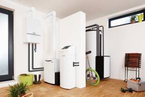
Figure 5.
Components of the Micro-CHP system of VaillantecoPower 1.0: wall-mounted gas-fired peak-load condensing
boiler (left), Micro-CHP unit and heat-transfer module with system controller
(center), multi-function cylinder with 300 liter or 500 liter capacity and
external heat exchanger for domestic hot water (right). Image source: www.Vaillant.com
In Figure 6
two scenarios of heat and power supply of a building are compared. On the one
hand there is a power generation with a coal-fired power plant together with a
gas boiler on site and on the other hand there is a micro-CHP on site. In this
example it turns out that the micro-CHP appliance can save 30% of the primary
energy compared with the low-efficient power plant solution.
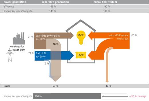
Figure 6.Comparison between a separated and a micro-combined heat and
power generation. Image source: www.ASUE.de
A product
example of a fuel cell-based micro-CHP unit called “BlueGen”
is shown in Figure 7. The natural gas-fired unit works
with a high temperature solid oxide fuel cell (Figures
8 and 10) and
can generate up to 2 kW electrical output with up to 60% efficiency (nettcv). Then with the utilization
of the simultaneously generated thermal output up to 1 kW W the total
efficiency of the “BlueGen” can increase above 80%.
For this case of operation the CO2-reduction could be 50% and more
compared with a separated heat and power generation of average existing energy
efficiency.
Ongoing
tests just try to find out how far the “BlueGen” can
cover the annual heat consumption and also the annual electrical consumption of
single-family or two-family houses in a power-led mode with a peak load boiler
and an optimized heating water buffer cylinder in addition (1).
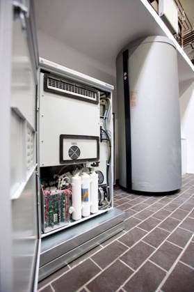
Figure 7.
In front with about the size of a washing machine the fuel cell-based micro-CHP
unit “BlueGen” of Ceremic
Fuel Cells Ltd. together with a different heating water test buffer cylinder
(1). Laboratory of Heating Technology at Cologne University
of Applied Sciences/Germany (http://www.f09.fh-koeln.de/fakultaet/personen/profs/klaus.sommer/00835/).
Image source: www.Rheinenergie.com
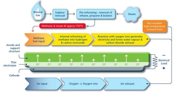
Figure 8.
Functional principle of the high temperature Solid Oxide Fuel Cell (SOFC);
source: Ceramic Fuel Cells Limited. Image source: www.cfcl.com.au
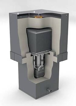
Figure 9.Opened “BlueGen” with the high
temperature solid oxide fuel cell stack in the upper part.Laboratory of Heating Technology at Cologne University of Applied
Sciences/Germany (http://www.f09.fh-koeln.de/fakultaet/personen/profs/klaus.sommer/00835/).
Compared
with separately generated heat and power the gas-fired micro-CHP appliances
with stirling engine,
internal combustion engine or high temperature solid oxide fuel cell save
energy and reduce CO2-production for old and new one- or two-family
houses. The heat-led “Stirling engine” and “Internal
combustion engine” are designed for 1 kW electrical output with an
electrical efficiency of 15% and 26.3% and CHP-generated thermal output of 2.5 kW
or 6 kW. Together with a peak load boiler the thermal output of these
appliances varies up to around 28 kW dependent on the chosen performance
of the peak load boiler. The high temperature solid oxide fuel cell is designed
for power-led operation with a very high electrical efficiency up to 60% and an
electrical output up to 2 kW together with a thermal output up to 1 kW.
(1) Two-year
research project (2011-2013) “Analyzing of the real operating characteristics
of a high-efficient fuel Cell-based Micro-CHP in order to find out the best
possible application for residential buildings and to get real system
characteristics”; project leader Klaus Sommer. Funded
by KlimakreisKoeln (www.klimakreis-koeln.de), Rheinenergie
(www.rheinenergie.com) and Cologne University of Applied Sciences (www.fh-koeln.de).
Follow us on social media accounts to stay up to date with REHVA actualities
0