

Stay Informed
Follow us on social media accounts to stay up to date with REHVA actualities


The technological combination of solar thermal systems with heat pumps continues to be a highly topical subject in the market of sustainable domestic hot water and space heating concepts. The main background for this development is the expected increase of efficiency for both, the solar thermal system and the heat pump due to synergetic effects resulting from the mutual interaction of these two sub-systems. Solar thermal energy can be used for example to provide the heat pump with higher heat source temperatures, which is beneficial to its performance factor, while the solar collector’s degree of efficiency rises simultaneously due to lower return temperatures in the solar loop when using the heat pump or an additional buffer store for this purpose as second heat sink. Nonetheless, objective performance test methods for such combined systems are not yet common standard. In this context field tests with different combined solar and heat pump systems installed in several single family houses in Germany are being performed by ITW within the project “WPSol”. In this paper a novel combined solar thermal and heat pump system using an ice store for domestic hot water preparation and space heating in single family houses, in the following named solar ice store system, is presented as one selected example of the investigated system concepts. The solar ice store system consists of different types of solar thermal collectors in combination with a brine to water heat pump which utilises an ice store as only heat source. The system’s functionality and the monitoring procedure are described and first results are discussed.
During the past years, a variety of combined solar thermal and heat pump systems with different conceptual designs have appeared on the European market, claiming that higher seasonal performance factors (SPF) of the overall systems can be achieved than with traditional, separated heating systems. However, uniform and objective criteria for the evaluation of the combined solar and heat pump systems’ thermal performances are not available up to now. Because of this corresponding test and assessment procedures are needed in order to be able to determine the energetic performance and the environmental impact of combined solar thermal and heat pump systems in an objective manner.
Therefore, international efforts are currently being made, e.g. within the IEA SH&C Task 44 and HPP Annex 38 “Solar and Heat Pump Systems”[1] [1]. In parallel, the research project “WPSol” (Performance testing and ecological assessment of combined solar thermal and heat pump systems) has been initiated by ITW in order to develop performance test methods for such combined systems [2], [3]. Key activities within this project are the development of a dynamic performance test procedure for heat pumps using the new heat pump test facility established at ITW, the extension of the CTSS[2] test method towards combined solar thermal and heat pump systems, the development of numerical models for specific components and TRNSYS simulations of complete systems, life cycle analyses for the characterisation of ecological aspects and field tests, i.e. in-situ monitoring of combined solar thermal and heat pump systems in real building environments.
Broad field tests of separate system technologies (such as solar thermal systems and heat pump systems) have been performed already for heat pump systems only [4], [5] and for solar thermal combi systems without heat pumps [6], [7] but not yet for the combination of solar thermal and heat pump systems. Although some of these combined systems have been monitored as single cases, a systematic study for this system category is still missing. Therefore, such field tests based on in-situ monitoring are being performed within the project WPSol as well as within Task 44/Annex 38 in order to determine the thermal performance of combined solar thermal and heat pump systems under real operating conditions.
The aim of this monitoring is on the one hand the detection of installation errors, optimisation of the operation behaviour of the entire system and controlling functions for different operation modes as well as the dimensioning of the collector field and storage capacity, etc. On the other hand, measured data are necessary for the validation of numerical simulation models of combined solar thermal and heat pump systems. The combined solar thermal and heat pump systems which are monitored within the project WPSol represent a broad spectrum of different concepts. Seven systems have been installed in Germany, at locations between Osnabrück in the north down to Füssen at the southern border to Austria. Five of these systems have already been equipped with measuring equipment and monitoring is running. In the following, one example of the systems under investigation is described in more detail.
This system consists of an earth buried latent heat store using water/ice as the only heat source for a brine to water heat pump. The ice store is charged with the heat delivered by solar absorbers (uncovered solar collectors) on the roof which also collect heat from the surrounding air during times with no or low solar irradiation. In addition, two flat plate solar collectors are used for charging a conventional small domestic hot water store on a higher temperature level than the ice store. The two types of solar thermal collectors are connected in a parallel way and the system controller decides, which collector type is being operated at a time, depending on the temperatures in the collector loops, in the domestic hot water store and in the ice store (c.f. Figure 1a and Figure 1b).
|
|
Figure 1a. Solar thermal flat plate
collectors (left), absorbers (right). [Source: ITW]
Figure 1b. Ice store. [Source: A. Bühring]
This system has been developed for two main reasons. On the one hand it intended to be an alternative for brine to water heat pumps with borehole heat exchangers at locations where borehole drilling is not possible /not allowed (e.g. due to ground water protection or other authorisations). On the other hand it has proven to be rather difficult to supply brine to water heat pumps with solar energy. With borehole heat exchanger systems regenerated e.g. with unglazed solar collectors (c.f. [8]) it is in general not feasible to store solar energy in the ground in a seasonal way, speaking about single family houses with only one or two boreholes. Especially if an aquifer is crossing a borehole, the solar heat is removed rather quickly and cannot be recovered later on. Furthermore, flat plate collectors might be damaged by condensation from air moisture due to low operation temperatures, when providing energy to the ground as additional heat sink. Another option for the integration of solar energy into a heat pump system is the direct coupling of the solar loop to the primary circuit of the heat pump without a buffer store. The problem with this approach is that especially during the space heating periods solar radiation is not always available as heat source for the heat pump.
The solar ice store system makes use of the traditional heat sources ground and ambient air and additionally couples solar energy into the system. The major difference of this system to other classical combined solar thermal and heat pump systems is the ice store that is used for storing solar thermal energy, geothermal energy and ambient energy from the air at a low temperature level in order to act as the only heat source of the heat pump (c.f. Figure 2).
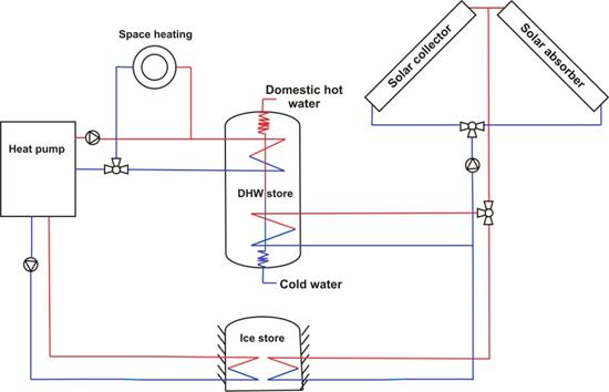
Figure 2. Simplified hydraulic scheme of the solar ice store system.
This ice store is a concrete tank with a volume of 12 m³ filled with water and buried into the ground. Polyethylene pipes as heat exchanger loops are placed inside the store for charging and discharging (c.f. Figure 1b). This water or ice store, respectively, is in principle comparable to a usual cistern, but it is also used as latent heat store. As the brine to water heat pump extracts more and more heat from the water store, the water will freeze to ice. The crystallisation enthalpy available during this process is additionally available for energy storage. Due to the occurring phase change this type of water store is called an ice store. As heat transfer fluid between the ice store and the heat pump an antifreeze fluid consisting of a water/Tyfocor mixture is used (ethylene glycol basis, melting point −15°C).
In the following, technical data of the several components of the solar ice store system which is being monitored by ITW and the building description of the house in which it is installed are described:
· Single-family house, 1 flat, 2 persons; Year of construction: 2010
· Location: Louisendorf, Hessen, Germany
· Heated living area: 175 m², floor heating system
· Brine to water heat pump with capacity 6 kW and integrated 220 l domestic hot water store, COP 4.6 at B0/W35[3], refrigerant R410A, scroll compressor
· 2 x 2.25 m² solar flat plate collectors and 2 x 4 m² solar absorbers
· 12 m³ ice store (latent heat store, storage medium: water/ice)
The system is being monitored since autumn 2011. Data are collected once
per minute with an Ennovatis Smartbox as
data logger and transferred once per day via a GSM mobile connection to ITW. Pt
1000 temperature sensors are used for measuring ambient temperatures, room
temperatures (boiler room) and flow and return temperatures of the three brine
loops: two solar loops and ice store to heat pump loop (primary circuit of the
heat pump). The solar radiation is measured with a Si cell sensor and the
ambient moisture with a hygrometer. Heat meters consisting of an ultrasonic
flow meter and two Pt 500 sensors each, are used for monitoring the heat flow
in the space heating loop and the domestic hot water loop including
circulation, recording flow and return temperatures and volume flows.
Turbine-type volume flow meters are used for measuring the heat quantity in the
three brine loops (two solar loops and primary circuit of the heat pump).
Electricity meters are used for the determination of the electric energy
consumed by the heat pump, the electric heating element included in the heat
pump, the solar loop pump, space heating loop pump, the circulation pump of the primary loop
of the heat pump and the controller. In addition, the status of two three-way valves
and the solar loop pump is monitored by means of a simple “on/off” signal in
order to track which solar collector is in operation and which store is being charged
at a certain time.
In Figure 3, monthly energy balances for the solar ice store system are shown in kilowatt-hours for the months January 2012 until July 2012. The central small bar of each column depicts the useful energy including heat losses. At the outer part of each column, the energy sources are displayed. They consist of solar gains from flat plate collectors to the DHW store, heat transferred from the ice store to the heat pump, electrical energy consumed by the heat pump and by the electric heating element.
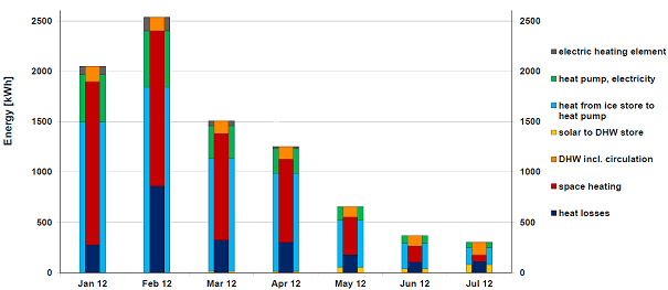
Figure 3. Monthly energy balances of the monitored solar ice store system[4].
The seasonal performance factor of the heat pump (SPFHP) was calculated as
![]()
with QSH – space heating, QDHW – domestic hot water, Qlosses – heat losses, Qsolar to DHW – solar energy to DHW store, Qel. heating element – heat delivered by electric heating element, Pel, HP – electricity consumption of the heat pump. SPFHP reached a value of 4.37 over the shown period of seven months, considering produced heat including heat losses, and 3.22 for produced useful heat only.
On the other hand, the thermal performance of a solar thermal system can be characterised by the fractional energy savings fsav, prim defined as the energy consumption of the solar thermal system (Qaux) compared with the energy consumption of a conventional reference system using a gas boiler (Qref):
![]() with
with
![]()
![]()
As primary energy ratios fPEfactors of 1.1 for natural gas and 2.6 for the German electricity mix were used. Parasitic energies as electricity consumption of circulation pumps and controlling are not included in the value of Qaux,.according to EN 12976. Qlossesdescribes the heat losses of a conventional water store as a fixed value. The solar ice store system reached fractional energy savings of 33% for the period shown above, which means that about one third less primary energy has to be used as compared to a conventional gas boiler.
In general, the solar contribution to domestic hot water preparation is rather low for this system. This is due to the splitting of the solar collector loops, allowing for either charging the DHW store by the flat plate collectors or charging the ice store with the solar absorbers only, at a certain time. Because of this the flat plate collectors are in operation only during a few hours per day, when solar irradiation is highest, i.e. at noon time. It can be recommended to change this operational mode for future system designs.
The ice store has been completely frozen
during winter time and the lowest temperature measured in the brine coming from
the ice store was −8.1°C in February (as flow temperature in the primary
loop of the heat pump). In Figure 4 solar gains to
the ice store and to the DHW store are shown together with temperatures in the
ice store and the heat from the ice store used by the heat pump. During winter
time, when the ice store is colder than the surrounding earth, geothermal gains
exist, while during the summer period more solar energy is transferred into the
ice store than is extracted by the heat pump. In the latter case, the ice store
is being regenerated by solar thermal heat and some losses occur towards the
surrounding ground depending on the temperature difference between the ice
store and the ground.
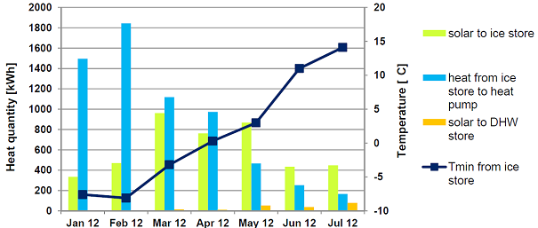
Figure 4. Solar gains transferred to the ice store and to the DHW store, heat gained by the heat pump and minimal temperatures in the ice store shown as monthly values for January – July 2012.
Seven combined solar thermal and heat pump systems are being monitored in a field test in Germany by ITW within the project WPSol. One of these systems, the so called “solar ice store system” with a brine/water heat pump, has been presented in this paper. Furthermore, the monitoring equipment and procedure have been described briefly and first measurement results have been shown. Monitoring is still on going, so final results cannot be presented yet. This kind of field test, in combination with appropriate laboratory performance test methods and transient system simulations, is crucial for the development of standardised performance test methods allowing for a detailed analysis and comparison of the many different system concepts available on the market.
The Project WPSol is partly funded by the German Federal Ministry for the Environment, Nature Conservation and Nuclear Safety (Bundesministerium für Umwelt, Naturschutz und Reaktorsicherheit BMU) under grant number 0325967A. The authors gratefully thank for the support and carry the full responsibility of the content of this publication. Thanks are also addressed to our industrial project partners for their contributions.
[1] IEA SH&C Task 44/ HPP Annex 38 Newsletter, http://www.iea-shc.org/Task44/newsletter/
[2] A. Loose, H. Drück, N. Hanke, F. Thole, “Field test for performance monitoring of combined solar thermal and heat pump systems”, in Proceedings of the ISES 2011 Solar World Congress, August 28 to September 2, 2011, Kassel, Germany, ISBN: 978-3-9814659-0-7.
[3] A. Loose, B. Mette, S. Bonk, H. Drück, “Development of performance test methods for combined solar thermal and heat pump systems”, in Proceedings of the 5th European Solar Thermal Energy Conference ESTEC 2011, October 20th – 21st , 2011, Marseille, France.
[4] M. Miara, D. Günther, K. Kramer, T.
Oltersdorf, J. Wapler, 2011, “Wärmepumpeneffizienz – Messtechnische
Untersuchung von Wärmepumpenanlagen zur Analyse und Bewertung der Effizienz im
realen Betrieb” – Kurzfassung des Abschlussberichtes. Fraunhofer ISE, Freiburg,
Germany (in German).
[5] Lokale Agenda-Gruppe 21 Energie in Lahr,
Germany, 2006, „Zweijähriger Feldtest Elektro-Wärmepumpen am Oberrhein – Nicht
jede Wärmepumpe trägt zum Klimaschutz bei”. http://www.agenda-energie-lahr.de/leistungwaermepumpen.html (in German).
[6] Combisol
Project, 2010. Standardisation and Promotion of Solar Combi Systems. Final
report,http://www.combisol.eu.
[7] J. Ullmann, B. Mette, H. Drück, “Evaluation of Solar Combisystems – Recommendations for improving the
thermal performance”; in Proceedings of the ISES 2011 Solar World Congress,
August 28th to September 2nd, 2011, Kassel, Germany, ISBN:
978-3-9814659-0-7.
[8] E. Bertram, J. Glembin, J. Scheuren and G. Zienterra, 2009, "Soil regeneration by unglazed solar collectors in heat pump systems", in Proceedings of the ISES 2009 Solar World Congress, Johannesburg, South Africa.
[1] IEA: International Energy Agency, SH&C: Solar Heating and Cooling
Programme, HPP: Heat Pump Programme.
[2] CTSS: Component Testing – System Simulation; as standardised in EN 12977 series.
[3] COP =
Coefficient of performance at operating point brine at 0°C (source temperature)
/water at 35°C (sink temperature), determined according to EN 14511.
[4] The
heat meter for measuring heat from the ice store failed for February, because
of which the value for this month has been calculated from the electricity
consumption of the heat pump using a mean “COP” of 4.29 - (heat source +
electricity)/electricity – as mean value of the neighboring months January and
March.
Follow us on social media accounts to stay up to date with REHVA actualities
0