

Stay Informed
Follow us on social media accounts to stay up to date with REHVA actualities
|
| |
MikkMaivelTallinn University of Technologymikk.maivel@ttu.ee | Martin
KonzelmannWTP
Wärmetechnische Prüfgesellschaft mbHmailbox@WTP-Berlin.de | JarekKurnitskiTallinn University of Technologyjarek.kurnitski@ttu.ee |
Emission losses of heat emitters are important topic especially in the case of low energy buildings. It is reported that radiators with serial connected panels can provide 11% energy saving (Therm X2 technology) and this has been argued with up to 100% higher radiation heat transfer and also shorter heating up time of radiator. In the case of serial connected panels, the hot water flows first through the front (room-side) panel and then to the back (wall side) panel, Figure 1. The cooled water then returns to the heating pipework. The idea of serial connection is to increase the room side surface temperature of the radiator which will increase radiation heat transfer and operative temperature.
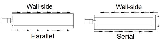
Figure 1.Studied radiator types with parallel and serial connected panels.
The objective of this study was to quantify the effect of parallel and serial connected radiator panels on emission losses and energy use with controlled laboratory measurements and dynamic simulation. The motivation was to show which differences can be measured in the laboratory and how these can be generalized to annual energy performance of conventional and low temperature radiator systems.
The limitation of the heat emission standard EN15316-2.1: 2007 is that the calculation procedure is fully based on air temperature. In reality different radiators have some effect on radiant temperature and the operative temperature is the basic parameter of thermal comfort standard ISO 7730:2005. The operative temperature is calculated as an average of air and means radiant temperature and is the temperature a human being is sensing. For exact comparison, the measurements and simulations are needed to be conducted at the same operative temperature, which was taken into account in this study.
Heat emissions of two radiators were measured in the test chamber with cooled surfaces conforming EN 442-2:2003 requirements. The radiators were 2-panel radiators physically of the same size, 0.6 m height and 1.4 m length, with parallel and serial connected panels and two convection fin plates in between, both types 22-600-1400. The rated heat output of Parallel was 2 393 W and for Serial 2 332 W at over-temperature ΔT 50 K according to EN 442-2:2003. Figures 2 and 3 illustrate the measurement arrangement and measurement points of temperatures.
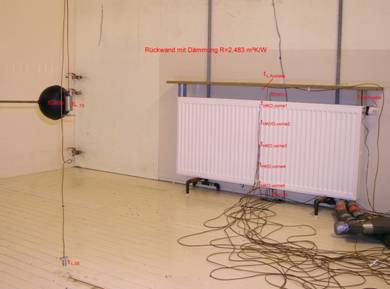
Figure 2.Photo of the measurement arrangement.
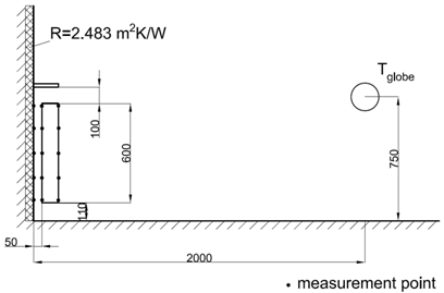
Figure 3. Radiator and temperature measurement points locations. The room floor area is 4.0 by 4.0 m and the room height 3.0 m.
Two flow temperatures were used, 50°C and 70°C. Both measurement cycles were repeated (Test 1, Test 2) in order to control the repeatability. The thermostat with the set point as close as possible to 20°C in all tests changed the water flow rate with respective changes in the return water temperature according to the heating need. The same thermostat was used in the measurements for both radiators tested. All tests were started with heating up step change.
The flow temperature of 50°C led after the step change to stable operation, where heat output from water flow decreased from about 900 W to 800 W level, corresponding to a situation where internal heat gains are close to 15% of nominal heat output, Figure 4.
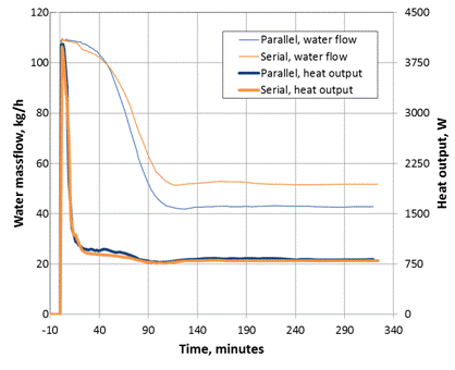
Figure 4. Test 1 with 50°C flow temperature: water massflows and heat outputs from water side.
An average front and rear panel’s surface temperatures show higher front panel and lower rear panel temperature in the case of Serial radiator, Figure 5. Water massflow stabilized to significantly lower level in parallel radiator and it was estimated that 3% higher heat output of Parallel radiator at ΔT 50 K increased to about 10% higher heat output at ΔT 25 K.
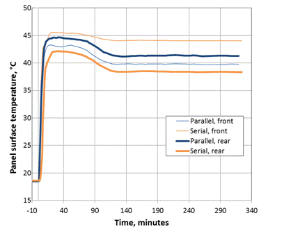
Figure 5. Front and rear panel surface temperatures in 50°C Test 1.
Heat output results were analysed for stabilized period of 130 to 320 minutes. Serial radiator used about 3% less energy in Test 1, but about 3% more energy in Test 2. Because the operative temperatures were not exactly the same, the cooled room surfaces temperature Ts was adjusted with analytical room heat transfer model described in (Maivel et al. 2014). The adjustment was done in both directions to test the validity of the model. Results are reported in Table 1, showing that at equal operative temperatures, the heat output of Serial radiator was by about 2% smaller and 4% higher in Test 1 and 2 respectively (the effect of the adjustment about 1%). Analytically calculated net radiation from the front panel of radiators was 120 W and 148 W for Parallel and Serial, corresponding to 15% and 18% radiation share respectively.
Table 1.Analytically calculated adjusted values of temperatures and heat outputs of radiators.
Test 1 | Test 1 | Test 2 | Test 2 | |
Top 19.39 →
19.58 | Top 19.58 →
19.39 | Top 19.33 →
19.51 | Top 19.51 →
19.33 | |
Air, Ta,
adjusted, °C | 20.16 | 20.00 | 20.05 | 19.90 |
Cooled surf., Ts,
adjusted, °C | 18.58 | 18.28 | 18.58 | 18.29 |
Parallel 50°C, heat output, W | 815.1 | 824.9 | 713.1 | 722.4 |
Serial 50°C, heat output, W | 798.7 | 807.3 | 745.0 | 752.7 |
Saving of Serial, % | 2.01 | 2.14 | -4.48 | -4.20 |
The tests at 70°C flow temperature corresponded to oversizing of radiators by about factor 2 (roughly 1 600 W vs. 800 W). Initial room temperatures were reasonably close in tests with both radiators which enabled an exact comparison of dynamic response during the heating up step change of about 3°C. In the case of Parallel, initial room air and surface temperatures were about 0.1°C lower, but Parallel radiator reached to the same temperature as Serial in 9 minutes. After that the air temperature curves were almost identical with slightly higher maximum value for Parallel at 43 minutes, Figure 6. After the heating up phase the thermostat valve was not able to keep stable temperature in both cases because of oversized radiators.
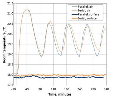
Figure 6.Dynamic step response of the room air and surface temperatures in 70°C Test 1.
IDA-ICE simulation software with standard water radiator model was used to model the EN 442-2 test room and a typical residential room with the same dimensions. In the case of the test room, the radiator was located on internal wall and other 3 walls, floor and ceiling were external ones, Figure 7. In the case of a residential room the radiator was located on external wall with a window and there was also another external wall. The residential room had exhaust ventilation without heat recovery. The simulation was run at −22°C outdoor temperature to compare the differences in heat outputs and all year round with Estonian TRY for annual heating energy.
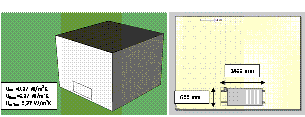
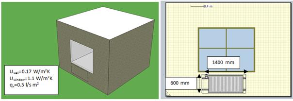
Figure 7.Simulated EN 442-2 room (upper) and a residential room (lower) in IDA-ICE model.
In the simulation a PI controller was used which kept the operative temperature set point of 19.5°C with high accuracy. In the case of EN 442-2 test room the U-values were selected so that heat losses were about 800 W at outdoor temperature of −22 °C. The IDA-ICE radiator model provided identical front panel surface temperature for Parallel radiator when return temperature was about 6°C higher than that in the measurements. To achieve the measured front panel surface temperature of Serial radiator the flow temperature was increased to 57.6°C. With these settings, the front panel surface temperatures were the same as in the measurements for both radiators and the simulation resulted in nearly the same heat emission of radiators, Table 2.
Table 2. Simulation results of EN 442-2 test room described in Ch. 2.3. All values at −22°C outdoor temperature.
| Parallel | Serial |
Flow
temperature, °C | 50.0 | 57.6 |
Return
temperature, °C | 39.8 | 43.4 |
Front panel
surface temperature, °C | 39.8 | 44.1 |
Rear panel
surface temperature, °C | 39.8 | 44.1 |
Air
temperature, °C | 20.69 | 20.58 |
Front
panel qfront,
W | 178.7 | 227.1 |
Convection
qcr,
W | 624.7 | 576.2 |
Back
side qb,
W | 0 | 0 |
Total
heat output qtot,
W | 803.4 | 803.3 |
In the case of a residential room, heat losses of about 630 W were slightly smaller compared to 800 W in the laboratory tests and some adjustment in flow temperatures was needed to have identical front panel surfaces temperatures. Simulated heat outputs show the difference of 1.9 W corresponding to the saving of 0.3% by Serial radiator, Table 3. In annual energy simulation Serial radiator provided heating energy saving of 0.7% and slightly higher front panel surface temperature as shown in Figure 8.
Table 3. Simulation results of a residential room described in Ch. 2.3. All values are at -22°C outdoor temperature, except the annual energy use.
| Parallel | Serial |
Flow
temperature, °C | 53.0 | 58.7 |
Return
temperature, °C | 38.3 | 43.1 |
Front panel
surface temperature, °C | 39.9 | 44.1 |
Rear panel
surface temperature, °C | 39.9 | 44.1 |
Air
temperature, °C | 19.61 | 19.48 |
Flow
temperature for backwall correction, °C | 57.7 | 53 |
Rear
panel surfaces temperature at corrected flow temperature, °C | 41.4 | 38.4 |
Front
panel qfront,
W | 179.2 | 227.7 |
Convection
qcr,
W | 446.8 | 396.8 |
Back
side qb,
W | 8.6 | 9.2 |
Corrected
back side qb,
corrected, W | 8.8 | 8.4 |
Total
heat output qtot,
W | 634.6 | 633.7 |
Corrected
total heat output qtot,
W | 634.8 | 632.9 |
Annual
heating energy use, kWh/(m2 a) | 64.9 | 64.5 |
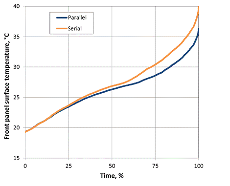
Figure 8. Duration curve of the radiator front panel surface temperatures (100% = 8 760 h).
· Laboratory measurements showed in the first test 3% lower and in the second test 3% higher heat emission of Serial radiator. The differences between the tests were higher than the declared accuracy of the EN 442-2 test room of +/- 1% and were caused by very small but continues swings in water flow rates and temperatures. The measurement setup used did not reached the complete steady state and was not able to quantify the differences between tested radiators, however indicating that these differences were very small if they existed at all.
· Simulated results of EN 442-2 test room with front panel surface temperatures of radiators identical to the measured values showed 0.11°C lower air temperature in the case of Serial radiator, but exactly the same heat emission of both radiators, because of more intensive radiation heat exchange in the case of Serial radiator.
· Simulated results of a typical residential room showed by 0.3% smaller heat emission at design outdoor temperature and by 0.7% smaller annual heating energy use in the case of Serial radiator. Therefore the radiator on external wall with higher front panel temperature resulted in a quantifiable energy saving approving the importance of radiant temperature as phenomena, but in terms of energy savings there was no considerable difference between studied radiators with parallel and serial connected panels.
· Serial radiator had 4°C higher temperature of the front panel that resulted in slightly higher radiation share, 18% relative to 15% for Parallel radiator in 50°C test. The rear panel temperature of Serial radiator was by 3°C lower that may have some energy saving effect in the case of poorly insulated walls.
· Parallel radiator showed slightly faster dynamic response and higher heat output which resulted in slightly faster heating up time. By 3% higher heat output of Parallel radiator at ΔT 50 K increased to about 10% higher heat output at ΔT 25 K which gives some advantage to Parallel radiator in low temperature heating systems.
1. Therm X2 -
Technology: Potential cost savings.
http://www.kermi.com/EN/Waerme-Design/Energiesparrechner/index.phtml.
2. EN 15316-2-1:2007. Heating Systems in
Buildings Method for Calculation of System Energy Requirements and System
Efficiencies Part 2–1: Space Heating Emission Systems, CEN 2007.
3. ISO 7730:2005. Ergonomics of the thermal
environment. Analytical determination of thermal comfort by using calculations
of the PMV and PPD indices and local thermal comfort criteria, ISO 2005.
4. EN 442-2:1996/A2:2003 Radiators and
convectors - Part 2: Test Methods and rating, CEN 2003.
5. Maivel M, Konzelmann M, Kurnitski J. Energy
Performance of Radiators with Parallel and Serial Connected Panels. Accepted
for publication in Energy and Buildings.
6. IDA-ICE, IDA Indoor Climate and Energy
4.6, http://www.equa-solutions.co.uk/.
Follow us on social media accounts to stay up to date with REHVA actualities
0