Stay Informed
Follow us on social media accounts to stay up to date with REHVA actualities

When measuring the airtightness (or air permeability) of a building, there is a crucial question that needs to be addressed before starting work: What is the objective of the measurement?
This question, however, might be obscure for most people and may need refinement.
There are various reasons why one could measure the airtightness of a building:
· To check compliance with a building code or contract (e.g. n50£ 2 h-1);
· To check the effectiveness of new construction details (compared with other details in other buildings);
· To calculate the building’s energy performance;
· To find and seal leaks;
· …
There are also different parts of a building that can be tested:
· The entire building;
· The thermally insulated part of the building;
· A new part of the building;
· One apartment in the building;
· All the apartments on a given floor;
· A block of offices in a factory;
· …
Hence, defining the objective of the test is essential for the operator who needs answers to practical questions:
· What part of the building is to be tested?
· What are the rules governing the test?
· What are the intentional openings in the envelope of this part of the building?
· What HVAC systems and other equipment are present in this part of the building?
All of this leads to the final question: What preparation does the building require?
Preparation of the part of the building subject to the test (hereafter called “the building”) is specifically addressed in ISO 9972:2006 [2] and EN 13829:2000 [1], where different methods are described depending on the purpose:
· Method A (test of a building in use);
· Method B (test of the building envelope);
· Method C (test of the building in use) (not available in EN 13829).
In the current revision of ISO 9972 [3], the third method is replaced by a ”free” method intended for specific purposes such as checking compliance with energy performance regulations. It thus opens up the possibility of preparing the building in accordance with a national regulation while still complying with the standard.
A point in common with all three existing methods is that all doors and windows in the building envelope must be closed. Another common point is the opening of all interconnecting doors within the building (note that the present exception for cupboards and closets will probably be deleted in the revision of ISO 9972).
In addition to these easily accessible openings and a number of secondary ones like post boxes or cat flaps, the main preparation work relates to HVAC systems.
First, all devices taking air from or removing air to the outside must be turned off: heating systems with indoor air intake, mechanical ventilation and air conditioning systems, kitchen hoods, etc. Since test operators generally are not HVAC engineers, instructions for operation should be available if needed.
It is important to understand that measuring a building’s airtightness involves pressurising or depressurising the envelope typically at 50 to 100 Pa. Therefore measures must be taken to avoid diverting combustion gases or polluted air from their intended routes and venting them instead into occupied spaces.
In some cases, e.g. when open gas boilers in apartments are connected to the same chimney, it might be necessary to turn off the boilers of all apartments in the building, even if only one of them is being tested.
Second, all intentional openings in the building envelope dedicated to HVAC systems must be treated according to the measurement method. The three possible treatments are closed, sealed or open (Table 1).
Table 1: Treatment of the intentional openings in function of the test method (ISO/CD 9972:2012 [3]).
Classification
of openings | Method 1 Test
of the building in use | Method 2 Test
of the building envelope | Method 3 Test
of the building for a specific purpose |
Ventilation openings for natural ventilation | Closed | Sealed | Closed, sealed or open as specified |
Openings for whole building mechanical ventilation or air conditioning | Sealed | Sealed | Closed, sealed or open as specified |
Openings for local mechanical ventilation or air conditioning (intermittent use) | Closed | Sealed | Closed, sealed or open as specified |
Windows, doors and trapdoors | Closed | Closed | Closed, sealed or open as specified |
Openings not intended for ventilation | Closed | Sealed | Closed, sealed or open as specified |
When openings must be closed for the test, leaks in the closing system are taken into account in the global air leakage rate of the building. This means that the choice of HVAC components such as closable externally-mounted air transfer devices can be of great importance, not only with regard to ventilation but also with regard to the building’s airtightness.
The same consideration could apply to smoke dampers or shut-off dampers for ventilation systems, cooker hoods and open fires.
When openings must be sealed for the test, their tightness depends on various factors:
· The skill and caution of the operator;
· The accessibility of the opening;
· Technique and material.
Remember that the highest pressure exerted on the building envelope during an airtightness test is approximately 100 Pa, which represents 10 kg/m². Thus, sealing works must be able to withstand this pressure. However, this is not always easy with large louvres for example (Figure 1).
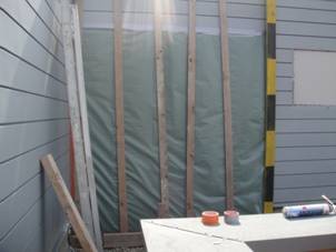
Figure 1. Sealing a large louvre can prove to be a difficult task.
Sealing the mechanical ventilation systems is often necessary. There are three options:
· Sealing the air terminal devices;
· Sealing the air intake and exhaust;
· Sealing the main ducts.
Sealing the air terminal devices (ATDs) is often an easy job in single dwellings but can be very tedious in multi-family buildings or in office buildings for example. The most often used technique consists of removing the ATDs from the ducts and replacing them with rubber bladders (Figure 2). Alternatively ATDs can be sealed with adhesive tape.
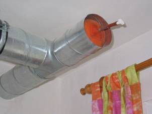
Figure 2. Rubber bladders can be useful for sealing ventilation ducts.
Another option is sealing the air intake and exhaust vents, but this often requires access to the roof or the top of a wall, which might entail specific security measures.
The third option consists of sealing the main ducts just before or after the air handling unit (AHU). This, however, requires access to the inside of the ducts through the AHU or a partial dismantling of the ducts, work that cannot be done by the test operator (Figure 3). Proper inspection panels in these ducts might be very useful here.
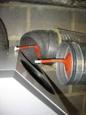
Figure 3. Sealing the main ducts just before or after the air handling unit is an option, but it generally requires dismantling the ducts.
To eliminate the need to seal the ventilation systems, shut-off dampers could be installed in the air intake and exhaust ducts. These of course should be sufficiently airtight when closed, in order not to degrade the results of the airtightness test. These dampers would also be useful when taking shelter in buildings is necessary, e.g. in the case of a large-scale outdoor pollution release.
It is also important to note that the airtightness of the ventilation ducts can influence the results of a building’s airtightness test. During the test, air indeed could leak out of or into the ducts within the building envelope, and again leak into or out of the ducts outside the building envelope. Sealing the ducts precisely where they go through the building envelope could avoid this problem, but it is generally not feasible in practice. Making the ducts airtight is therefore recommended not only for ventilation purposes.
Chimney flues for boilers, air heaters or stoves are often open (or even closed in the case of stoves) during the airtightness test of the building. They, however, could be sealed if required for the test. In this case, access hatches primarily intended for soot removal can be very useful (Figure 4).
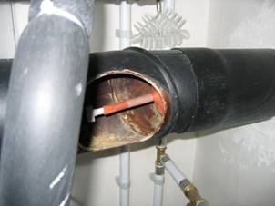
Figure 4. Access hatches in chimney flues can be very useful if the flues need to be sealed for the airtightness test.
[1] EN 13829:2000 Thermal performance of buildings - Determination of air permeability of buildings - Fan pressurization method (ISO 9972:1996, modified).
[2] ISO 9972:2006 Thermal performance of buildings - Determination of air permeability of buildings - Fan pressurization method.
[3] ISO/CD 9972:2012 Thermal performance of buildings - Determination of air permeability of buildings - Fan pressurization method.
Follow us on social media accounts to stay up to date with REHVA actualities
0