Stay Informed
Follow us on social media accounts to stay up to date with REHVA actualities
The UK’s Airtightness testing & Measurement Association (ATTMA) is a trade body that represents the UK’s leading air-tightness testing and consultancy firms. Most of the work undertaken by these firms is for the builders of new housing and buildings, who are required to prove that they have achieved the required level of air-tightness in their buildings in order to satisfy Building Regulations. |
In England and Wales, it has been a requirement that all types of new buildings and dwellings have to be tested since 2006. Prior to this, most buildings were neither designed nor built with air-tightness in mind; primarily because there was no requirement for testing. Consequently it is generally accepted that older UK houses and buildings are on average quite ‘leaky’. Indeed, research conducted by the Building Research Establishment (BRE) over 10 years ago determined that a typical UK dwelling leaked at a rate of 11.48 m³, per m² of their external envelope, per hour at an air pressure differential (between inside and outside of the envelope) of 50 Pa (see below). The minimum standard permissible under current UK Building Regulations is 10m³/(m².hr) @50 Pa, although usually in order to attain overall compliance with calculated CO2 limits, a far lower (better) figure has to be both specified and achieved.
A frequent point of discussion among ATTMA members is the fact that, set against this background of generally ‘leaky’ existing building and housing stock in the UK, there is an opportunity to significantly improve the energy and carbon performance of our existing building and housing stock by means of simple, low-tech but effecting air-sealing measures. The barrier to this seems to be in lack of awareness as to the extent of the benefits that can be realised by this approach. This is reflected in the range of attitudes that air-tightness specialists come up against amongst builders, building inspectors and even building managers/owners; ranging from some who regard air-tightness as being as fundamental and vital as weather-tightness to those who regard it with apathy, scepticism or even hostility.
What is needed is more reliable evidence as to the positive impact that improved air-tightness can deliver in a typical UK building or dwelling, alongside an appropriately designed and controlled ventilation system. Aside of those whose at the extremely sceptical end of the aforementioned spectrum, most building professionals, and indeed the general public would acknowledge the general principle that a less air-leaky building is likely to be more energy and carbon efficient, and more comfortable for the occupants (providing the ventilation is appropriate). However, the problem is the lack of a sense of scale or quantity.
With this in mind, in 2010 the ATTMA decided to attempt to provide some evidence by means of commissioning a research project by the BRE, who are themselves members of ATTMA and acknowledged experts in air-tightness, but who are also unrivalled in their ability to undertake building performance research projects of this type.
The brief given to BRE was to undertake research to demonstrate the impact on the space heating load in a typical UK dwelling that arises when the air-permeability of its external envelope is improved. For this purpose, the BRE provided two of its purpose-built ‘test houses’, located on the BRE’s, Watford site. The two dwellings are largely identical mid-terrace houses situated side-by-side, with construction details that are typical of millions of existing UK dwellings.
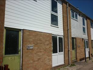
The two dwellings in the test are largely identical mid-terrace houses situated side-by-side, with construction details that are typical of millions of existing UK dwellings.
The test methodology was that of whole-house co-heating testing, the principle of which is described below. In short, it is a method of accurately determining the aggregated thermal losses of an unoccupied building. The testing was undertaken by Mr Arron Perry and Mr Nigel Waldron from BRE’s Building Technology Group overseen by Mr David Butler, between November 2010 and March 2011. Air-permeability testing was provided by Jamie Best of Melin Consultants.
The two similar houses were used in order to provide a ‘control’. For each, the co-heating testing and analysis was conducted in two phases: firstly with them both having an equally high average air-permeability, then secondly with one having its air-permeability left high, while the other had its air-permeability made much lower by means of sealing up its fabric. Each “phase” of testing lasted several weeks in order to gather sufficient data for analysis.
Air permeability testing was used to determine the air-permeability of each house at the beginning and end of each testing phase.
Measured air permeability of test houses in the test phases 1 and 2.
Phase
1 Air Permeability | Phase
2 Air Permeability | |
House 1 | 15.60 | 15.60 |
House 2 | 15.78 | 4.88 |
The air-permeability levels for both houses were deliberately increased for the first phase of the testing in order to create a larger margin of measured improvement. This was done by the air-tightness tester deliberately introducing holes into the external walls and ceilings of the houses until repeated air-permeability testing showed that both houses were exhibiting an air-permeability of between 15 and 16 (m³/(m².hr) @50 Pa). They then both subjected to co-heating testing to demonstrate establish the baselines for each. A few weeks later, House 2 was sealed and tested down to just under 5 (m³/(m².hr) @50 Pa), while House 1 was left unchanged. The measurement of heat loss then resumed, with House 1 effectively acting as the ‘control’.
The co-heating test is a practical method of determining the combined fabric and infiltration heat loss of an unoccupied house. It involves electrically heating the houses to a constant indoor temperature. Correlation of the measured electrical heat input and solar heat gains with indoor and outdoor air temperature difference allows an estimation of the whole house heat loss coefficient.
Since the tests were undertaken during winter, the room air temperature in each house was controlled to a constant temperature between 18 and 23°C using electric heaters so that an average temperature difference of between 10 and 20°C was maintained between room and outside air temperature.
Electric convector heaters were installed in the main rooms and were controlled on a zone basis by accurate proportional temperature controllers with remote temperature sensors located centrally in the zone at approximately 1.5 m above the floor. The electricity consumed by the fans was accounted for by including them in the metered heater supplies. One pulse output kWh electricity meter (1 000 pulses per kWh) was provided in each zone. To maintain an even temperature distribution throughout the houses, all internal doors were fully open and air circulation fans were used to mix the internal air. The fans were installed on poles above each heater to prevent stratification and encourage air circulation without excessively high air speeds.
External air temperature was measured by a shielded sensor near the north elevation of the terrace. Solar irradiance was measured by a Kipp and Zonen pyranometer mounted on a weather mast on the north field area of the BRE site.
In order to minimise unaccounted for heat gains and losses all external windows and doors and other openings were closed and all electricity consuming appliances and lighting was switched off. Access to the houses was also restricted to an absolute minimum during the duration of the co-heating tests.
Electricity consumption, room air temperatures, external air temperature and solar irradiance were continuously measured and recorded using battery powered data loggers (Eltek SQ1000) with a recording interval of 15 minutes.
Solar heat gains were determined by analysing the measured solar irradiance data using a simple window solar heat gain model. The window model took account of the window glass area, orientation and glazing type. Raw solar irradiance measured at each house on a horizontal plane was apportioned to each vertical orientation using the fraction of hourly CIBSE cooling load data on each orientation (CIBSE Guide A, Table 5.19 Solar cooling loads).
The calculated solar gains were added to the measured electrical heating energy to determine the total heat input necessary to maintain the specified mean internal air temperature. The houses were assumed to have low / medium thermal mass and therefore it was assumed that the majority of solar heat gains received during a day and absorbed into the house fabric would be released to the house interior in the same 24 hours period. Therefore the correlation of heat input with mean internal and external air temperature difference was assessed on a 24 hours or daily basis.
The room air temperature in each unit was controlled to a range of fixed temperature values using electric heaters so that an average temperature difference of at least 10°C was maintained between room and outside air temperature. Solar heat gains were determined by analysing the measured solar irradiance data using a simple window solar heat gain model.
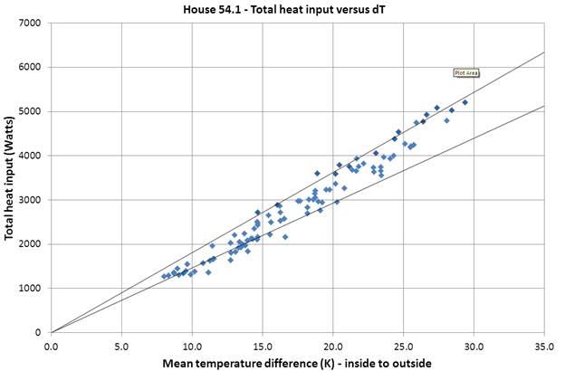
Linear regression analysis yielded the following heat loss coefficients (with forced y-axis intercept of y=0):
Heat loss coefficients calculated from the measures heating energy use during the test phases 1 and 2.
Phase 1 Heat Loss Coefficient (W/K) | Phase 2 Heat Loss Coefficient (W/K) | |
House 1 | 146.6 to 181.3 | |
House 2 | 151.5 to 179.4 | 105.0 to 116.3 |
The difference between the lower and upper regression line coefficients for each data set is assumed to be the effect of wind speed.
Their relative heat loss performances can be attributed to almost entirely the difference in fabric air-permeability as all other factors remained the same for both; in particular, the climatic conditions that they were exposed to during the testing phases.
The overall conclusion was this: the reduction in heat loss in House 2 resulting from the air leakage sealing measures, corresponding to an improvement in air permeability from 15.78 to 4.88 (m³/(m².hr) @50 Pa), was between 46.5 and 63.1 W/K, equivalent to between 31 and 35% reduction in heat loss.
ATTMA argue that it is reasonable to assert that there exists a linear relationship between air-tightness and heat loss (assuming all other factors remain constant). Therefore, it would for example be reasonable to assert that an improvement in air-tightness from, say 11.5 to 5 m³/(m².hr) @50 Pa would yield a reduction in heat loss in the order of 15%. Therefore, if typical UK houses were remedially air-sealed from their current state (i.e. an average leakage rate of 11.5 m³/(m².hr) @50 Pa to a not unreasonable level of 5 m³/(m².hr) @50 Pa, then one could expect to see an average saving in heating costs of up to 15% over the life of the property.
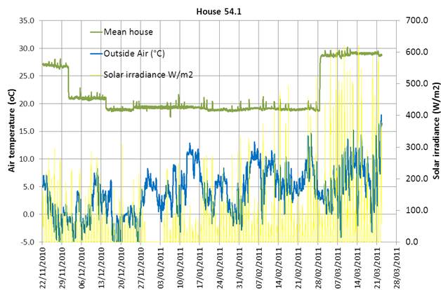
House
1:
House
2:
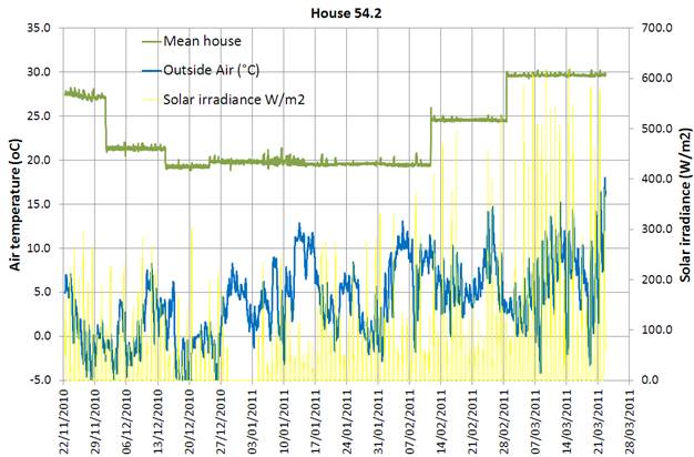
Indoor and outdoor temperature, and solar irradiation during the test for both houses.
House 2:
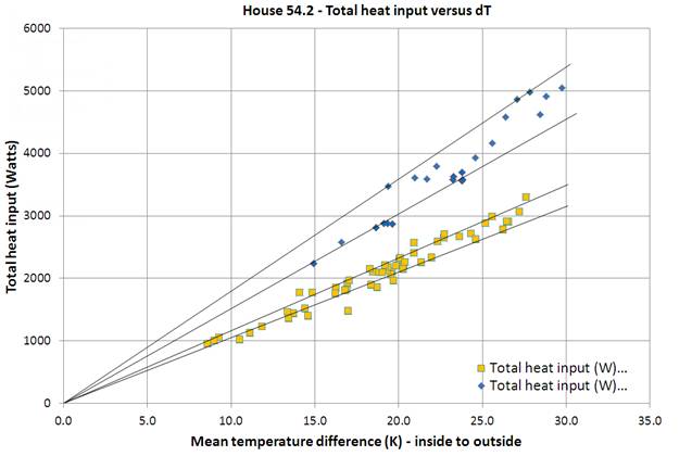
Heat loss coefficients for both houses with different airtightness of building envelope. Upper lines correspond the permeability of 15.78 and lower lines 4.88 (m³/(m².hr) @50 Pa).
Obviously this saving is at risk of being eroded by occupant behaviour and in particular by losses from ventilation. Nonetheless, weighed against the relatively minimal one-off cost of locating and permanently sealing the air-leakage sites, the argument is compelling.
Much of the technical content of this article is taken from the BRE’s Report number 271-943, “Co-heating Tests on BRE Test Houses Before and After Remedial Air Sealing” By David Butler and Arron Perry.
Follow us on social media accounts to stay up to date with REHVA actualities
0