


Stay Informed
Follow us on social media accounts to stay up to date with REHVA actualities
|
|
Mads MysenSINTEF Building and InfrastructureNorwaymads.mysen@sintef.no | Peter G. SchildSINTEF Building and InfrastructureNorway |
|
|
Axel CabléSINTEF Building and InfrastructureNorway | John WoollettSwegon Air AcademySweden |
· energy-efficient and
accurate DCV system
· balancing procedures
· handover procedures
When correctly implemented, Demand-Controlled Ventilation (DCV) can reduce the energy consumption of ventilation by more than 50 % (Maripuu, 2009). However, evaluation of real energy use demonstrates that the energy saving potential is seldom met (Mysen et al., 2010). DCV-based ventilation systems must become more reliable to close the gap between theoretical and real energy-performance. These unfortunate experiences with DCV have many causes, including: inadequate specifications and handover documentation, balancing report not suitable for DCV, communication errors and lack of knowledge about DCV systems among decision makers. Based on this experience from case-studies, an expert group has developed new requirements and handover documentation (Mysen and Schild, 2013). The work is carried out in the Norwegian R&D-project reDuCeVentilation (http://www.sintef.no/Projectweb/reDuCeVentilation/).
DCV systems are ventilation systems in which the airflow rate is
controlled automatically according to a measured demand at room level. This
means that DCV systems must have a feedback control, for instance a sensor in
the room giving a continuous measurement of the indoor air quality. This signal
is then used to control the airflow rate according to the desired indoor air
quality level.
VAV stands for Variable Air Volume. It is a broader term than DCV, as it encompasses all systems with variable airflow rate, irrespective of the type of control. Only VAV systems that control the airflow rate according to a measured demand in the room, and not according to a preset value, are considered as DCV in this paper. Normal VAV dampers in DCV systems are denoted by DCV damper in this paper.
The commissioning, balancing, and control of a DCV system consist of
the following work steps (Figure 1).
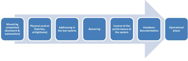
Figure 1.
Recommended work steps subsequent to the mounting of the ventilation system.
This paper addresses the following critical control points during the commissioning
of a DCV:
· energy-efficient and accurate DCV-system
· balancing
procedures
· handover
procedures
Specific Fan Power (SFP) is normally required and controlled at maximum airflow rate. However, a DCV system will typically have airflow rates between 30 and 80% of the maximum airflow rate, depending on diverse factors for dimensioning and on the minimal ventilation rate. At maximum airflow rate, there are only small differences between the system’s SFP depending on the control strategy (Figure 2, r = 1), but at lower airflow rates (Figure 2, r < 1), there are major differences depending on the control strategy. It is important to require a maximum SFP-value for two operating scenarios: maximum airflow rate and reduced airflow rate, in order to ensure an energy efficient control strategy.
The most important control points are presented in Figure 2.
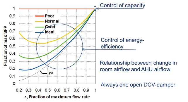
Figure 2. The most important control points. Measurement of SFP with partial load, control of the compliance between airflow rate at room level and total airflow rate, and control that there is always one DCV damper in max open position with the help of the Building Management System (Schild&Mysen, 2009).
Airflow rate accuracy should be controlled. A variation of the airflow rate in any room should correspond to approximately the same variation of the total airflow rate through the air-handling-unit (AHU). This test will reveal whether a pressure-controlled DCV system redistributes part of the airflow rate because of insufficient precision or wrong placement of the pressure sensor.
Critical components such as CO2-sensors should be checked on-site. One control point for CO2-sensors is to check whether they all give the same CO2 concentration (ppm-results) when the building is empty during the evening/night.
Deviations during commissioning are normal and should be expected. Unfortunately, there is seldom time planned ahead to improve the system. A better solution is to, in advance, agree upon a model for economic compensation to take into account the deviations from the requirements which affect the energy consumption. Economic compensation caused by deviation between required and measured SFP-value, has been tested in Norway.
A DCV system is a dynamic system and should be tested and tuned-in for both summer and winter conditions. There should be an inspection, function test and review of the DCV- system after a period of normal operation, e.g. 1 year.
There are several DCV systems and these principles are defined and described by Mysen (Mysen and Schild, 2011). Some of the DCV principles require special balancing procedures; this paper addresses "Pressure Controlled DCV” and “Damper optimised DCV".
Pressure-Controlled DCV (PC-DCV) correspond to the traditional DCV systems (Figure 3). The purpose of static pressure-control is to indirectly control the airflow rates by controlling the pressure in a strategic duct position. PC-DCV requires installation of active DCV units controlling supply and exhaust airflow rates to each DCV room/zone. Controlling fan speed to maintain a constant static fan pressure rise, will result in unnecessary throttling along the critical path during most of the AHU's operating time, and therefore unnecessary fan energy use. The duct path with the greatest flow resistance from the AHU to any terminal is called the ‘critical path’, and is used to dimension the necessary fan pressure rise.
One unfortunate experience concerning PC-DCV systems, is that minor changes in room demand just redistribute the airflow rate in the duct system, while the airflow rate in the AHU remains more or less constant. The consequence is that no energy saving is achieved, or that the amount of supply air is insufficient. This is normally caused by inadequate precision or wrong placement of the pressure sensor, for example a placement to close to the AHU or next to a branch. A rule of thumb is to place it ¾ out in the main duct.
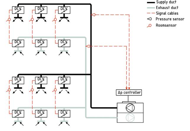
Figure 3. Pressure-controlled DCV system. The fan speed is
controlled to keep the static pressure in the main ventilation duct constant,
at the location of the pressure sensor.
The main purposes when balancing a PC-DCV system are:
· controlling
the placement of the pressure sensor
· setting
the right pressure set point
In addition, the balancing will reveal connection and communication
errors.
Balancing of a PC-DCV system consists of the following steps:
· Control
that all the DCV units have supply voltage and no polarity error
· Control
that the pressure sensor is mounted on a location with stable static pressure
or uniform velocity profile, by performing measurements over the duct cross section
with a Pitot-tube or a hot-wire anemometer.
· Select a
pressure set point which is slightly higher than necessary. This can be deduced
from pressure drop calculations, or empirically.
· Program
the actual maximum and minimum airflow rate values (Vmax and Vmin)
on each DCV damper and set the dampers to automatic mode. Control
that all the DCV dampers get the maximum airflow rate, and read the opening
rate. Find the index damper, which is the damper with the highest opening rate.
· Adjust
the pressure set point until the index DCV damper gets the maximum airflow rate
without throttling (about 80 % opening rate). You have then found the energy
optimal pressure set point, which is the lowest pressure set point which
provides the right airflow rates according to the designed values.
· Complete
the VAV control form. The completed control form should be included in
the documentation of the ventilation system.
Damper-optimised DCV consists in controlling the airflow
rate in the main duct according to the position of the dampers, such that at
least one of the dampers is in a maximum open position (Figure 4). The purpose is to ensure minimum fan energy consumption by looking
for a minimum pressure rise over the fan. This is achieved if one duct path
(critical path) is always open. With damper-optimised
DCV, the required
airflow rate, the supplied airflow rate as well as the damper angle are
recorded for all the DCV dampers. This information is sent to a controller
which regulates the fan speed.
Balancing of DCV units in damper-optimized systems is very simple, and
consists in specifying minimum and maximum design airflow rate for each DCV unit.
This can be done either through the bus-system or by connecting a programming
device directly on the DCV units. Various programming devices are used by the
different suppliers.
Balancing of a damper-optimised DCV system consists of the following
steps:
· Control
that all the DCV units,room sensors/ room
regulators etc. have supply voltage and no polarity error.
· Program
the actual maximum and minimum airflow rates values (Vmax and Vmin)
on each DCV damper and set the dampers to automatic mode.
· If the
DCV units do not give the expected response, check the polarity on the supply
voltage.
· Complete
the VAV control form. The completed control form should be included in the
documentation of the ventilation system.
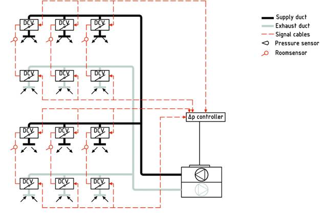
Figure 4. Damper-optimised DCV system.
Problems during operationoccur most
oftenformaximumorminimumairflow rates.Tests shouldthereforebe carried outforthese twooperatingsituations. For each ofthese
situations, it is necessary to consider eachDCV unitandto overridethe control signalfrom theroom sensor(e.g.temperature)in order to forcethe DCV unitto respectivelymaxandminairflow rate,and to documentboththe airflow rateand the opening rate.The opening ratetellswhether the DCV unitsworkwithin a
favorablerange (40 to 80%) and whether thepressureset point is balanced.
This requiresfourcontrol
measurementsperDCV unit.Sucha control
procedureisparticularly relevantforDCV systems withpressure-controlandlimited
controlpossibilities from the BMS.
A specialVAV controlformisdesigned for
thispurpose (Figure 5).
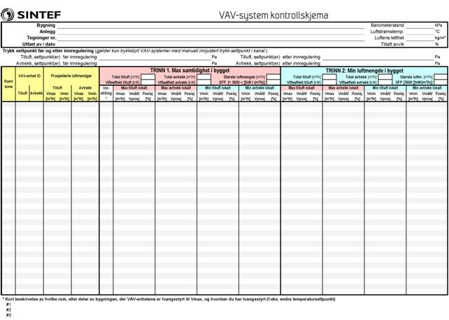
Figure 5.
Recommended VAV control form (http://www.sintef.no/Projectweb/reDuCeVentilation/)
Procedures for load tests at maximum and minimum loads/airflow rates
have been developed (Mysen and Schild, 2013).
Manual load
test are time consuming, and it has proven to be very
difficult to override DCV units during a load test. One should therefore strive
to automate the load test completely by programming it in the control panel, or
in the BMS. This has several advantages: it can be a complete test (not
spot-checking) with all combinations of overriding, it reduces costs
significantly, and can be repeated as often as needed (one time per year during
normal operation, or after changes in the system).
Follow us on social media accounts to stay up to date with REHVA actualities
0