


Stay Informed
Follow us on social media accounts to stay up to date with REHVA actualities
|
|
|
Thomas HartmannProf. Dr.-Ing.ITG Dresden Institute for Building Systems Engineering - Research and
Application | Christine KnausDipl.-Ing.ITG Dresden Institute for Building Systems Engineering - Research and
Application | Florian EibischB.Eng.ITG Dresden Institute for Building Systems Engineering - Research and
Application |
The air
flow around and through a building with several rooms belongs among the most
difficult issues of the aerodynamic. Exemplary for the complexity of the
influences are the interaction between adjacent buildings, the overlap of wind
and thermal lift, as well as the simple effect of an open or closed inner door.
In the specialist literature but also in the relevant standards, such as EN 15242:2007,
the physical models to calculate the determination of air flow rates in
buildings are described in detail. For the practical application of these
algorithms for example in the planning of ventilation systems a description of
mathematical approaches for iterative processes is missing. As suggested and
commissioned by the European Ventilation Industry Association (EVIA) an Excel
tool to calculate the air flow rates in buildings including infiltration on the
basis of EN 15242 was made by the authors. This Excel tool is generally
applicable even after reviewing this standard in the course of the EPBD mandate
480 (the future EN 16798-7 ”Energy performance of buildings – Part 7:
Ventilation for buildings – Module M5-1, M5-5, M5-6, M5-8 – Calculation methods
for the determination of air flow rates in buildings including infiltration”).
The
calculation algorithm is based on a mesh model. So-called mesh networks occur
in many technical areas, for example in gas and water supply networks. Each
building plan can be converted into a meshed system. For the calculation of the
airflows through a building the mesh method is a highly universal method also
for viewing complex flow processes. The consideration of internal and external
interference factors is possible. The aim of the method is to determine the air
mass flows through the flow paths of a building. The building must be converted
for the use of the method in a so-called airflow network that includes all flow
paths, and their characteristics in terms of pressure losses and pressure
profits, see Figure 1. This network consists essentially
of loops (links) and nodes (rooms).
|
|
Building plan | Airflow network representation |
Figure 1. Conversion of a building plan into
a meshed system.
Along a
loop the mass flow remains constant. In flow direction there is a pressure drop
caused by friction. Nodes are characterized by varying mass flows, but firm
pressure conditions.
To solve
this mesh network there exist a number of calculation methods. Together, all
have the need to form meshes. A mesh in this case represents a closed flow path
whose starting and ending points are identical.
The chosen mesh-based method needs a
specified mass flow distribution at the beginning. This should lead to the fulfillment of
all nodes conditions. During the solution process, the respective mass flows
are then constantly changed until the mesh-conditions are satisfied.
A very
common and well-proven mesh-oriented solution method is the Hardy-Cross method,
which is often used in water and gas distribution networks. Due to its easy
traceability and good data base, this method is implemented in the Excel tool.
There are
basically two types of these methods: Sequential and simultaneous process. In
the sequential method, each mesh is considered individually, taking into account
the outcome of the consideration in the next mesh. An iteration step is complete
when each mesh was calculated individually. In the simultaneous method always
all meshes of the system are considered simultaneously. So aconvergence
is achievedfaster. The disadvantage is the higher complexity of programming these
processes and the traceability of intermediate results is limited.
The
Hardy-Cross method is an easy understandable iteration algorithm and calculable
by hand. It is based on Newton’s approximation method.
Explaining application Hardy-Cross methodFor this
method, it is necessary to use a starting value x0 of unknown size. The closer this starting value to
the actual solution x0
of the system (equivalent to zero), thefaster convergence is achieved. In
the following recommendations the term convergence refers to situation when a
predetermined error bound is reached. At each iteration step a correction
increment is calculated, which is then subtracted from the initial value of
the iteration. The calculation of the correction increment k occurs by
solving equation (1).
This
procedure is used principally in the Hardy-Cross method. The variable x, which is modified during iteration,
is equivalent to the mass flow along a loop. The function of which the root
is determined describes the pressure balance along a closed loop system.
Therefore it is necessary to know the fixed pressure differences (pressure
sources), and the variable pressure differentials (flow resistance) and their
functional relationship along a mesh. The pressure balance along an arbitrary
loop m with o compounds can be calculated as follows:
The
functional relationship of flow resistance of a connection as a function of
the mass flow through this connection may be arbitrary. The flow resistance
depends normally on a coefficient and an exponent. According
to equation (2) the pressure balance is calculated along each mesh. This must
be differentiated according to the Hardy-Cross method with respect to the
mass flow rate in order to calculate the correction mass flow
Therefore,
the pressure balance and its first derivate are determined along a loop. The
resulting correction mass flow
This
correction mass flow is now subtracted from each mass flow, which is
contained in the compound. The corrected mass flows are then used as starting
values for the consideration of the next loop of the system. An iteration
step is complete when all meshes were once considered. To check the accuracy
of the resulting mass flows, the sum of the amounts of formed correction mass
flows of the iteration step is used. If the sum drops below a certain value,
the iteration procedure can be aborted and the results are displayed in the
corresponding form. | |||||||||||||||||||||||||||||||||||||||||||||||||||||||||
The handling of the tool has been made easier
for the user by using a color-scale showing if all required input data are
completely and in the right form (Figure 2).
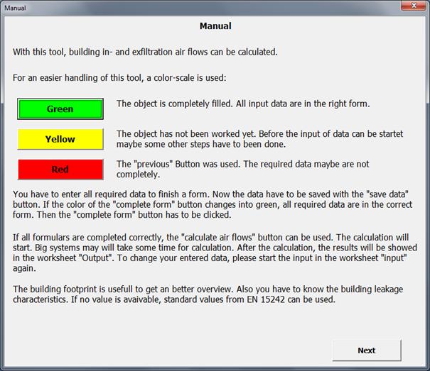
Figure 2. Information window – short description of the
calculation tool.
In general, by clicking on the ”Save data”
button all entered data are saved and can be used for the calculation. The
”complete form” button changes into green showing that all data are in the
correct form. Activating the ”Complete form” button closes the current input
mask and the ”Overview” window or the next input mask appears.
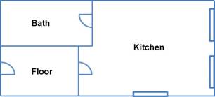
With the Excel tool it is possible to calculate
the air flow through the building with up to 20 rooms distributed over one or
more floors, see Figure 3. The maximum of connections (e.g. windows, doors, air inlets) of one
room is bounded to 20 connections. For each room a supply and/or exhaust air
volume flow can be defined by a ventilation system. It has to be pointed out
that the defined air volume flows are constant and independent of pressure
conditions in the building minimizing the calculation effort. The calculation
of the building air infiltration and exfiltration under steady-state conditions
is performed with constant conditions defined by the user, see Figure 4.
Figure 3. Floor plan of
a mid-terrace house (left: ground floor, right: upper floor) with supply and exhaust
air flow rate of the rooms (boundary conditions: 6 rooms, 15 connections, 2
floors, balanced ventilation system, temperature ratio of 80%).

Figure 4. Factors
influencing the air flow in building according to [Nowotny].
Using the defined conditions following data can
be determined / calculated:
· Aerodynamic pressure factor for each
connection of the building (Cp-value)
· air tightness, which is split
relatively (ratio of the area of the outer walls or fixed portion) to the
respective external connection
· pressure difference for each opening
Summing up, the
result of the tool are air flow rates for defined steady-state conditions in consideration of wind pressure, thermal
lift and – if there is one – the ventilation system.
In the input mask ”Overview” (Figure 5) under the heading project details and object details the user can provide several information. After choosing the calculation unit: m³/h, m³/s or l/s further input fields are enabled.
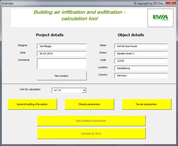
Figure 5. Filled input mask ”Overview” for the example with
enabled input fields.
The input mask ”General building information”
is divided into three aspects:
· General building information
· Information of the calculated flat
· Ventilation system
In the aspect ”General building information”
the user can provide details about:
· Number of rooms (up to 20 rooms
possible)
· Building height in m
· Width of the building (in wind
direction) in m
· Roof slope in °
· Leakage characteristics (n [relative
to indoor volume], q [relative to outer envelope] or w [relative to floor
area])
· Pressure difference of leakage
characteristics in Pa
· Value of air tightness in
m³/(h·m²)
· Exponent n (registered
default value 0,67)
In the aspect ”Information of the calculation
flat” the input field, which is needed for the calculation, is highlighted in
yellow depending on the selected leakages characteristics. The three possible
input fields are:
· Indoor volume in m³ (selecting n [relative to
indoor volume])
· Outer envelope in m² (selecting q [relative to
outer envelope])
· Floor area in m² (selecting w [relative to
floor area])
Information regarding the air-handling system
can be given in the aspect ”Ventilation system”, see Figure 6.

Figure 6. Input data regarding the ventilation system.
Figure 7 shows the filled input mask
”General building information” for the mid-terrace house.
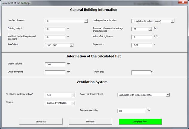
Figure 7. Filled input
mask "General building information" for the example after saving the
entered data.
In the input mask ”Climate parameters” (Figure 8) information regarding the
following values has to be completed:
· External (outdoor) temperature in °C
· Reference wind speed (at reference
height) in m/s
· Reference height in m (registered
default value 10 m)
· Wind direction
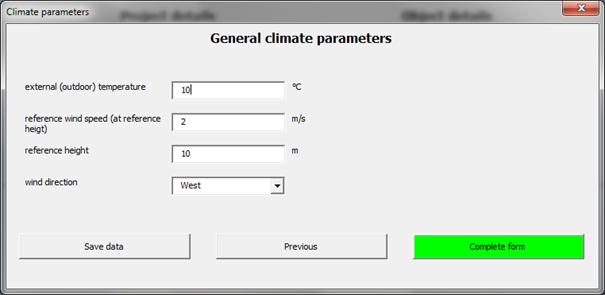
Figure 8. Filled input mask "General climate
parameters" for the example after saving the entered data.
Depending on the selection made in the input
mask ”General terrain information” (Figure 9) different input fields have to be filled with information from the
user:
· Terrain class (open terrain, country
or urban/city)
· Are there obstacles next to the
building?
If there are obstacles next to the building,
which are at least half of the height of the building further input fields are
enabled:
· Orientation of the obstacle(s) (north, east, south or west)
· Height of the obstacles in m
· Width of the obstacles in m
· Distance between building and
obstacles in m
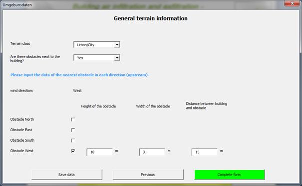
Figure 9. Filled input mask "General terrain
information" for the example after saving the entered data.
Before the rooms are configured, it is possible
to name the rooms for easy entry. If the possibility is not chosen, the rooms
will retain their nomenclature like ”room 1”, ”room 2” etc. and the
configuration of the individual rooms can start. If the possibility is chosen
to name the rooms, another window will open where the individual nomenclature
can be entered.
The data entered in this input mask ”General
information of the room” refer to the selected room and following values:
· Temperature in °C
· Volume in m³
· Height of the floor (relative to
ground) in m
· Air flow caused by ventilation system?
(depending to the selected ventilation system: supply air flow in m³/h, exhaust
air flow in m³/h, or both air flows in m³/h)
· Number of connections (doors,
windows etc.) (up to 20 connections per room possible)
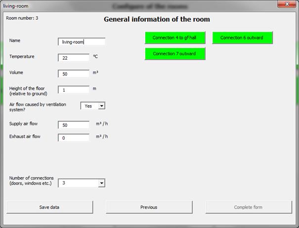
Figure 10. Filled input mask "General information of
the room" for the living-room (supply air space) of the mid-terrace house.
Figure 10
shows exemplary the input mask ”General information of the room” for a supply
air space.
In addition to the information about which room
is selected and the global connection number further data are required in the
input mask ”Connection data”, see Figure 11. Depending on which connection and which type is chosen further
information is necessary, for example
· Connection: Orientation
· Door (if closed): air tightness of
the door
· Wall: Outer area
· Air inlet: Differential pressure
Rooms with only one connection like storerooms
with a door and no window are not taken into account in the calculation. Under
steady-state conditions there is only very small air flow volume along the
joints of the door due to the thermal lift between the lower and the upper
joint of the door. Nevertheless, if these rooms should be taken into account in
the calculation the door has to be split into two or more connections with
different heights. The resulting air flow volumes are very small and there is a
short-circuit flow around the door. The calculated air exchange rate does not
represent the real local air exchange rate of the room.
Figure 11. Input data regarding the connections of a
room.
Figure 12 shows exemplary the input mask
”Connection data” for connections from the ground floor hall to the
living-room, the upper floor hall and outwards.
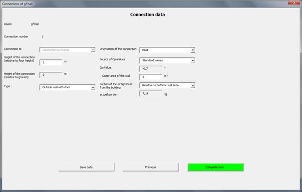
Figure 12. Filled input mask ”Connection data” for the
connection from ground floor hall to the outside of the mid-terrace house
(connection to outwards).
Activating the ”Calculate air flows” button the
calculation starts and the results are shown in the worksheet ”Output”, see Table 1and Table 2.
Table 1. Calculation
results for the mid-terrace house with regard to calculation details (excerpt).
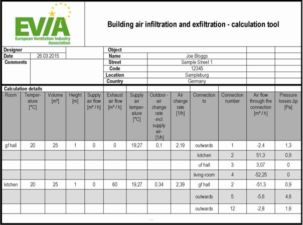
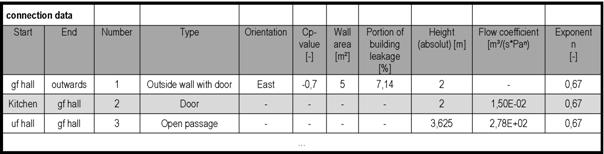
Table 2. Calculation results for the mid-terrace house with regard to connection
data (excerpt).
It is possible to calculate variants by changing
conditions like wind direction, air tightness of the building envelope,
ventilation systems etc. in relevant input masks. All changes have to be saved
and completed.
Changing the number of rooms (adding rooms or
reducing the number of rooms) can be done in the input mask ”General building
information” as long as there do not exist the first connection. After entering
the first connection it is not possible to change the number of rooms in this
project and a new project has to be started.
Changes of the connection of rooms like
orientation, type or increase the number of connections can be done without
problems in the relevant windows ”General information of the room”. However to
reduce the number of the connection, a new project has to be started or a saved
version has to be used.
On behalf of the European Ventilation Industry
Association (EVIA) an Excel tool was developed to for example use the in EN 15242
described physical models to calculate air flow rates in buildings for daily
work of building and system planers. This provides users with a convenient
facility to determine air flow rates room by room caused by leakages and
externally mounted air transfer devices under variation of essential boundary
conditions and under steady-state conditions. The Excel calculation tool can be
obtained free of charge and together with a detailed manual in the EVIA
download area (http://www.evia.eu/en/Media-Centre/Download/) of the EVIA
homepage (English or German version).
EN 15242:2007 Ventilation for buildings – Calculation methods
for the determination of air flow rates in buildings including infiltration.
prEN 16798-7:2015
Energy performance of buildings – Part 7: Ventilation for buildings –
Module M5-1, M5-5, M5-6, M5-8 - Calculation methods for the determination of
air flow rates in buildings including infiltration.
Nowotny, S. & Feustel, H.E. 1996. Lüftungs- und klimatechnische
Gebäudeausrüstung – Grundlagen und Berechnungsmodelle, Wiesbaden; Berlin:
Bauverlag.
Ventilation and air
conditioning building services – Basics and calculation models.
Background The air flow around and through a building with several rooms belongs among the most difficult issues of the aerodynamic. Exemplary for the complexity of the influences are the interaction between adjacent buildings, the overlap of wind and thermal lift, as well as the simple effect of an open or closed inner door. In the specialist literature but also in the relevant standards, such as EN 15242:2007, the physical models to calculate the determination of air flow rates in buildings are described in detail. For the practical application of these algorithms for example in the planning of ventilation systems a description of mathematical approaches for iterative processes is missing. As suggested and commissioned by the European Ventilation Industry Association (EVIA) an Excel tool to calculate the air flow rates in buildings including infiltration on the basis of EN 15242 was made by the authors. This Excel tool is generally applicable even after reviewing this standard in the course of the EPBD mandate 480 (the future EN 16798-7 ”Energy performance of buildings – Part 7: Ventilation for buildings – Module M5-1, M5-5, M5-6, M5-8 – Calculation methods for the determination of air flow rates in buildings including infiltration”).
Follow us on social media accounts to stay up to date with REHVA actualities
0