Stay Informed
Follow us on social media accounts to stay up to date with REHVA actualities

It is often claimed, or implicitly assumed, that the energy use of controlled fans in ventilation systems decreases in part load conditions by the cube (3rd power) of the load. That means that the energy use decreases from 100% to 12.5% if the air volume flow rate of the ventilation system decreases from full to half load. An analysis ([1], [2] and [3]) based on a mathematical model leads to the conclusion, that there are in fact some cases for which this “cube law” is nearly valid, but also, that in other cases it is far from being valid. Formula and diagrams have been derived that show how the energy consumption reduces with decreasing load, in dependence of the chosen control function type and other decisive influencing factors. Additionally to this insight in the validity of the cube law and the mentioned formulae and diagrams, which also are useful instruments for the control designer, the analysis resulted in new hourly calculation procedures to calculate the energy need for fans, which will be used in the future EN 16798-5-1 (draft [4]) and EN 16798-6-1 (draft [5]), belonging to the calculation standards in the new set of CEN/EPBD standards [6].
The
article gives
·
In the 1st part an overview of the analysis carried out to
study the impact of control on the energy use for fans in ventilation systems
·
and in the 2nd part the details to one of the results, i. e. the diagrams which supports the designer of control
in the selection of a suitable fan control function type for a multi zone
ventilation system.
Under the “cube law” or the “cube law for fans” we understand here the idea that the energy use of a fan is proportional to the cube of the air volume flow rate or of the part load ratio of the ventilation system. We distinguish between two cube laws, the cube law for the fan gas power
![]() (1)
(1)
and the cube law for the electrical power use of the fan
![]() (2)
(2)
where (cf. Figure 1)
qV = air volume flow rate
R = flow resistance
ηF = efficiency factor of the fan and its drive
PF,el is the electrical power use of the fan, i.e. the power input to the drive of the fan. PF,Gas is - according to [7] - defined by (5). It is therefore equal to PF,el if there were no losses in the fan and its drive, that means if the efficiency factor ηF were equal to 1.
The cube
law can be derived directly from the following equations (cf. Figure 1)
![]() (3)
(3)
![]() (4)
(4)
![]() (5)
(5)
![]() (6)
(6)
where
ΔpR = pressure difference over the flow resistance R
ΔpF= pressure difference over the fan
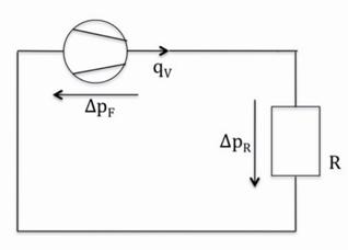
Figure 1.Node
model, that is under lied to the cube law for the fan power use.
The cube
law for PF,Gas can also be formulated with
dimensionless quantities
 (7)
(7)
where
![]() = normalized fan gas power
= normalized fan gas power
qV,Fld = qV at full load = design value for qV
PF,Gas,Fld = PF,Gas
for qV
=qV,Fld
![]() =part load ratio of the air volume flow rate
=part load ratio of the air volume flow rate
This
cube law (7) is visualized as dashed curve in Figure
7, and
repeated also as dashed curve in Figure 8 and as solid curve in figures 9–11.
The cube
law is an ideal law. In practice there are always more or less strong
deviations from this ideal law. These deviations depend on the operation
conditions, on the installed fan and its drive and on the applied fan control
function type.
·
It is important to distinguish between
○
Single zone ventilation systems, where the fan controls directly the air
flow rate through the zone
○
Multi zone ventilation systems, for which the air flow rate through a
zone is controlled by dampers (often as part of VAV-boxes). The fan control
allows to reduce the pressure in the air distribution network and by this to
reduce the energy use of the fan
·
For single zone ventilation systems it is important to distinguish
between
○
Continuous and staged (on-off, 2- stage, etc.) control
○
Open loop and closed loop control
·
For multi zone ventilation system it is important to distinguish the
following fan control function types
○
Control function type 0: No control
○
Control function type 1: Constant pressure control over the fan
○
Control function type 2: Constant pressure control over the air
distribution network
○
Control function type 3: Minimum pressure control
·
For multi zone ventilation systems it was possible to develop a relative
simple mathematical model that allows deriving formulae that give for all
control function types the normalized fan gas power as a function of a few
parameters summarizing the main influencing factors.
·
The main reasons for the deviations from the ideal cube law are
○
The fan efficiency factor ηF (fan inclusive its drive) is not
constant. It generally decreases with reducing part load ratio.
○
The air volume flow rate qV in single zone ventilation systems with on/off
or multi stage fan drives is for commonly used open loop fan control functions,
in contrast to closed loop control, usually higher than needed.
○
The pressure drops over not completely open zone control dampers in
multi zone ventilation systems causes in part load operation deviations from
the cube law.
·
It is important to distinguish between the part load conditions of the
ventilation system and that of the fan.
·
The results of the analysis are valid also for pump control in hydraulic
systems.
·
New hourly calculation
procedures
to calculate the energy use of fans (This result was the original motivation
for the analysis)
·
Simple instruments for the control
designer,
supporting him in selecting a suitable fan control function type: Formula and
diagrams that show how the energy use of the fan reduces with decreasing load,
in dependence of the chosen control function type and other decisive
influencing factors
·
Insight in the validity of the cube law
·
The results will be applied in the future EN 16798-5-1 (draft [4]) and EN 16798-6-1 (draft [5]), belonging to the calculation
standards in the new set of CEN/EPBD standards [6]. The standard EN 16798-5-1 will
replace EN 15241:2007 [8].
·
The results will be applied in the revision
of the SIA 2044 standard [9].
Figure 2 shows the node model on the
‘volume flow rate’-pressure- level, underlying the analysis for the case of a
multi zone ventilation system with two zones.
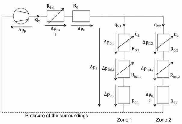
Figure 2.Node model underlying the analysis, shown for a multi zone ventilation system with two zones.
An important assumption in the derivation of the hourly method is that the fan control loops converge to a steady state, or to a quasi steady state in the case of staged control, within one calculation time interval of one hour. More details to the mathematical models and the assumptions underlying the analysis are given in [1] and partially also in [2], [3] and [5].
Four
different fan control function types are considered. Figures 3–6 show their control schematics for the case of two zones (each one with
one room) and the case of the supply air fan. For all types the air volume flow
rates of the zones are controlled by the local controllers CR1 and CR2 acting
on zone control dampers. Shown is the case where these controllers serve to
keep the CO2 concentration in the zone air close to a set-point
value, but they could also be zone temperature controllers.
The four considered fan control function types are:
·
Control function type 0: No control of the fan (cf. Figure 3)
·
Control function type
1: Constant pressure control over the fan (cf. Figure
4): The fan
controller C1 controls the pressure difference over the fan on a constant
set-point value
·
Control function type
2: Constant pressure control over the air distribution network (cf. Figure 5): The fan controller C1 controls the pressure difference between the
distribution network and the surroundings on a constant set-point value.
·
Control function type
3: Minimum pressure control (cf. Figure 6): The fan controller C1 controls
the pressure difference between the distribution network and the surroundings
close to the smallest possible set-point value. The smallest possible set-point
value is determined by an overlaying control loop with the controller C2, which
controls the pressure difference over the distribution network such that the
zone damper with the maximum opening will be close to completely open (in the
model 100%, in practice e.g. 90%). There are three possible versions of this
control function type: In the 1st version the controller C2 acts on
the control loop for the pressure over the distribution network, as shown in
figure 6, in the 2nd version the controller C2 acts
on a control loop for the pressure over the fan and in the 3rd version it acts directly on the fan drive
(C1 is no more necessary). Figure 6 shows that this control function
type requires an information link between the zone controller and the central
fan controller. Usually the communication network of the building automation
system is used for this link. Simulation based investigations to this control
function type can be found in [10] and [11].
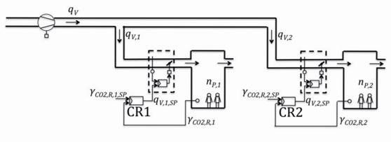
Figure 3. Control function type 0: No control of the fan.
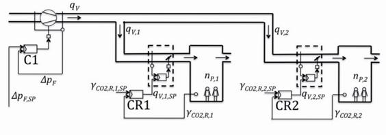
Figure 4. Control function type 1: Constant pressure control over the fan.
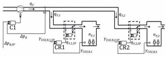
Figure 5. Control function type 2: Constant pressure control over the air distribution network.
Figure 6. Control function type 3: Minimum pressure control – version 1.
It was
possible to derive for each control function type a formula that give the
normalized fan gas power as a function of a few parameters summarizing the main
influencing factors. For the control function type 1 it is
![]() (8)
(8)
for 0 £ f £ 1
for
the control function type 2
![]() (9)
(9)
for 0 £ f £ 1
and
for the control function type 3
![]() (10)
(10)
for 0 £ f £ fmax
where
f = part
load ratio of the total volume flow through the fan as defined above
c = ∆pR,Fld / ∆pF,Fld
fmax = ![]()
= maximum part load factor fi of
the zone air volume flows (maximum over zones)
= f + Δf if part load diversity Δfis the given input parameter
fi = qV,i / qV,Fld,i = part load factor of
the zone air volume flow of zone i
qV,i = volume flow rate
in zone i
qV,Fld,i = qV,i
at full load = design value for qV,i
Δf = f − fmax= part load diversity =
a scale to measure the diversity of the part loads over the zones
The formulae are valid for any number of zones.
The formulae (8)–(10) allow to draw the diagrams shown in figures 7–11. The parameter ∆pR,Fld/∆pF,Fld is the ratio of the design pressure difference over the zone branches to that over the fan. The curve parameter for the control function type 3 is the maximum part load factor fmax(left side of the figure), or alternatively the part load diversity Δf(right side of the figure).
The diagrams in figures 7–11 show in which cases the cube law for the fan gas power is valid or nearly valid:
·
For control function type 2 and 3, if the ratio of the design pressure difference over the zone branches to that over the
fan is small. Type 3
does not bring a substantial improvement compared to type 2 in this case.
· For control function type 3, if the part load diversity is small (the cube law is exactly valid if the part load diversity is zero).
The diagrams in figures 7–11 serve as a useful instrument for the control designer, by supporting him in selecting a suitable control function type. Some rules for the selection from an energy point of view can directly been derived from the diagrams:
·
For a ventilation system with a small ratio ∆pR,Fld/∆pF,Fld i.e. for a ventilation system
for that the design pressure difference over the zone branches is small
compared to that over the fan (typically for the supply air pipe with a central
air handling unit with a high flow resistance and short zone branches) the
control function type 2 leads in part load operation to a fan energy
need that is substantially lower than that of type 1. Control function type 3
does not bring a substantial improvement.
·
For a ventilation system with a large ratio ∆pR,Fld/∆pF,Fld i.e. for a ventilation system
for that the design pressure difference over the zone branches is large
compared to that over the fan (typically for the exhaust/extract air pipe and
long zone branches) the advise for a selection depends on how often the system
is in which part load and in which part load diversity. The more frequently the
system is in part load operation with a small load diversity the more rewarding
is it to prefer type 3 to type 2 or 1. If the part load
diversity is at most time large, then type 1 is sufficient. Type 2 and 3 does not bring a substantial
improvement.
Whether type 1 should be preferred to type 0 cannot be found out from the shown diagrams. That depends on the characteristic curves of the fan. If the curves in the operation area are flat, then the advantage of type 1 compared to type 0 is not substantial.
A final selection of the fan control function type should also take into account other criteria as cost or for example the auto-tuning capability of the control function type 3, which can compensate for bad manual balancing of the pipe network.
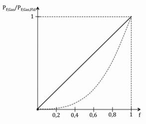
Figure 7. Control function type 1: Load dependency of the fan gas power
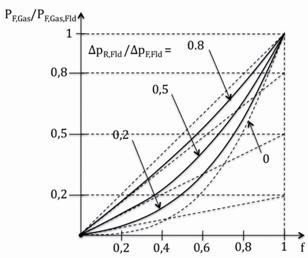
Figure 8. Control function type 2: Load dependency of the fan gas power for different ratios of the design pressure difference over the zone branches to that over the fan
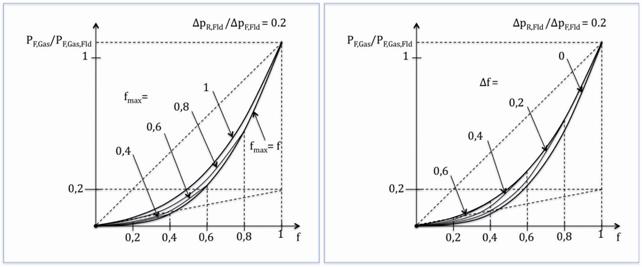
Figure 9. Control function type 3: Load dependency of the fan gas power for the case where the design pressure difference over the zone branches is small compared to that over the fan
Figure 10. Control function type 3: Load dependency of the fan gas power for the case where the design pressure difference over the zone branches is medium sized compared to that over the fan
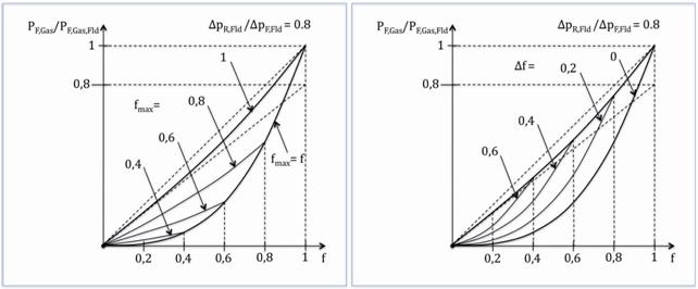
Figure 11. Control function type 3: Load dependency of the fan gas power for the case where the design pressure difference over the zone branches is large compared to that over the fan
[1] Tödtli Jürg, Berechnung des
Energieverbrauchs eines Gebäudes im Stundenschrittverfahren – Einfluss der
Gebäudeautomation auf die Ventilatorleistung, SIA Bericht für EnergieSchweiz,
Stand 2012-12-17.
[2] TödtliJürg, „Standard control description for CEN TC 371 – An example – Energy performance of buildings – Modules M5-6, M5-8 – Ventilation in buildings – Multi zone ventilation systems – Calculation method for the energy use of fans – Hourly data processing“, Version 2013-09-20.
[3] Tödtli Jürg, „Die dritte Potenz: ein Mythos? – Der Einfluss der Gebäudeautomation auf den Energiebedarf von Ventilatoren in HLK-Anlagen“, 18. Status-Seminar „Forschen für den Bau im Kontext von Energie und Umwelt“, ETH Zürich, 4./5. September 2014.
[4] prEN 16798-5-1, Energy performance of buildings - Modules M5-6, M5-8, M6-5, M6-8, M7-5, M7-8 - Ventilation for buildings - Calculation methods for energy requirements of ventilation and air conditioning systems - Part 5-1: Distribution and generation (revision of EN 15241) - Method 1, draft May 2015
[5] prEN 16798-6-1, Energy performance of buildings - Modules M5-6, M5-8, M6-5, M6-8, M7-5, M7-8 - Ventilation for buildings - Calculation methods for energy requirements of ventilation and air conditioning systems - Part 6-1: Technical Report – interpretation of the requirements in EN 16798-5-1, draft October 2014
[6] CEN/EPBD-standards = European standards to EPBD, where EPBD = Energy Performance of Building Directive = DIRECTIVE 2010/31/EU OF THE EUROPEAN PARLIAMENT AND OF THE COUNCIL of 19 May 2010 on the energy performance of buildings (recast). (One of the objectives of the revision of the CEN/EPBD-standards is to adapt them to the recast of this directive)
[7] COMMISSION REGULATION (EU) No 327/2011 of 30 March 2011 implementing Directive 2009/125/EC of the European Parliament and of the Council with regard to ecodesign requirements for fans driven by motors with an electric input power between 125 W and 500 kW
[8] EN15241:2007, Ventilation of buildings – Calculation methods for energy losses due to ventilation and infiltration in commercial buildings.
[9] SIA Merkblatt 2044, Klimatisierte Gebäude –
Standard-Berechnungsverfahren für den Leistungs- und Energiebedarf, Ausgabe
2011
[10] INTECOM: Integrated control strategies for improving energy management and comfort in new and existing buildings, EU Research project 1998-2001, Contribution by A.L. Dexter and Y. Zang.
[11] Plüss, Iwan, Menti Urs-Peter, VAV Optimizer,
Ermittlung des energetischen Einsparpotentials, Hochschule Luzern, Technik und
Architektur, Oktober 2005
The author thanks the Swiss Federal Office of Energy for the financial support of the analysis [1] under the Swiss Energy Program. Responsible for the content and conclusions is exclusively the author of the report.
Follow us on social media accounts to stay up to date with REHVA actualities
0