


Stay Informed
Follow us on social media accounts to stay up to date with REHVA actualities
|
|
|
Oddgeir GudmundssonDanfoss A/S, Heating Segment, Application &
Technology – Nordborg – DK | Jan Eric ThorsenDanfoss A/S, Heating Segment, Application &
Technology – Nordborg - DK | Marek Brand.Danfoss A/S, Heating Segment, Application &
Technology – Nordborg - DK |
When utilizing low-temperature district heating it becomes important to achieve good control at the consumer side to meet the required cooling of the supply. The low supply temperature as such is not a big concern for thermostatic radiator controls. When it comes to the domestic hot water the low supply temperature can cause challenges when it comes to Legionella growth. It is therefore important to apply domestic hot water preparation units that can prepare the hot water with minimized risk of Legionella growth. The best way to avoid Legionella is to minimize the domestic hot water installation volume and prepare the domestic hot water instantaneously when demanded. For single family buildings this can easily be done by right setup of the consumer heating interface and ensuring that the distance between the consumer interface and the point of usage is as small as possible and has less than 3 liters of water volume [1]. When it comes to multifamily buildings it becomes a bit trickier as from historical reason the domestic hot water is typically prepared centrally and then circulated around the building. The temperature of the circulation is then controlled to keep a minimum of 50-55°C, to prevent Legionella growth. This way of domestic hot water preparation puts a limit on how low supply temperature can be used by the district heating scheme or alternatively by other decentralized heat sources. To be able to reduce the supply temperature as much as possible it becomes a necessity to move the domestic hot water preparation in multifamily buildings as close to the point of use as possible. This can be achieved by applying flat stations at each flat [2]. The domestic hot water preparation is then moved from the basement to the flat station at each flat.
District energy has for the last couple of years been receiving increased awareness in energy strategy plans of governments and cities and is seen as one of the key drivers for reducing CO2 emissions by opening up for large-scale application of renewable heat sources. When looking on the generations of district heating (DH) it is clear that the supply temperature has been continuously decreasing [3]. With the increased share of energy efficient buildings the trend is becoming a must to ensure cost efficiency of the DH systems. Lower supply temperature means not only reduced heat loss from the DH network but also higher efficiency of the applied heat source and easier exploitation of low-grade renewable sources. It is therefore clear that low supply temperature gives both better economy and increased options for utilization of low-grade waste heat.
Although reduced supply temperatures have positive results on the energy efficiency of the heat generation process and the distribution there is another factor that needs to be considered, the heat delivery at the buildings. Traditionally the heating installations have been designed according to current norms. This generally means that the older the building is the higher supply temperature the heat emitters were designed for. This causes potential mismatch between low-temperature district heating (LTDH) and installed heat emitters in the buildings. However, this potential mismatch between LTDH and building heat installation design parameters are only applicable at a part of the heating season, most of the time it should be possible to fulfill the building heat demand using low temperature supply.
In general, there are three connection principles for connecting the space heating installation with the district heating network, a) indirect connected, b) direct connected with mixing loop and c) direct connected, see Figures 1 to 3. For multi-apartment buildings the same principles are applied in the flat stations. If the network pressure is higher than PN10, only indirect connections can be applied.
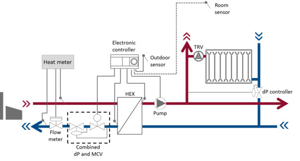
Figure 1. Indirect connected substation.
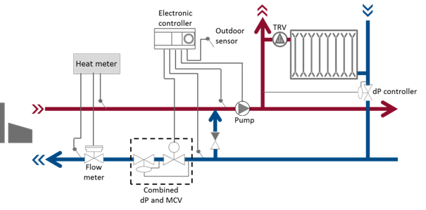
Figure 2. Direct connected substation with a mixing loop.
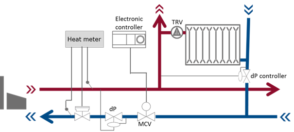
Figure 3. Direct connected substation.
In general a) is recommended due to hydraulic separation between the district heating network and the space heating installation. If direct connected system is applied the mixing loop is the recommended alternative to the indirect connection. If floor heating is applied, only a) or b) should be used.
When it comes to LTDH it becomes important that the space heating system is designed to operate with the low temperature supply. The heat emitting units in the buildings can be floor heating or radiators. Floor heating generally require temperatures less than 40°C, due to their large heating surfaces. Radiators however require higher supply temperatures, due to their small heating surfaces, to fulfill the heating demand. This means that floor heating systems fulfill the requirements set by LTDH and therefore from this point forward only radiators are considered.
Studies have shown that radiators in existing houses, from 1970s, have traditionally been oversized and can operate with low supply temperatures large part of the year and almost fully with only small building energy renovations [4].
Even in
non-renovated buildings from 1970’s, the heating system can operate with supply
temperature as low as 50°C almost 79% of the year and rarely needs supply
temperatures higher than 60°C (see graph below).
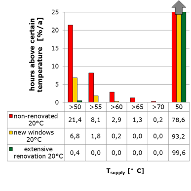
Percentage of hours during a year with required supply temperatures to achieve 20°C indoor temperature in typical 1970s building in Denmark.
Although space heating control when applying LTDH is in general the same as when applying traditional DH there are some points that differentiate. Due to the low supply temperatures it becomes very important to achieve accurate control to limit the flow rate and achieve the design cooling of the supply.
To minimize the risk of overflow in radiators thermostatic radiator valves (TRV) with a pre-setting function should be used. The purpose of the thermostat function is to adjust the flow to achieve the desired room temperature. The purpose of the pre-setting is to limit the maximum flow through the valve to the design demand. Properly set pre-set function will significantly increase the hydraulic balance in the heating loop.
To ensure proper operating condition for the TRV’s it is important to install a differential pressure controller. The differential pressure controller will ensure a stable differential pressure at the correct level across the heating installation, typically pr. heating riser of the building.
To limit the impact of wrong setting of the TRV’s a return limiter can be installed at the radiator outlets. The purpose of the return limiter is to ensure that a preset return temperature from each radiator is not exceeded.
When applying LTDH particular focus needs to be put in the DHW interface and the DHW installation. Due to the low supply temperature instantaneous DHW preparation is required along with optimum design of the DHW installation in terms of pipe distances and volume.
For supply temperature above 50°C it is possible to apply instantaneous DHW applications using high efficiency heat exchangers. The recommended DHW control is a proportional flow controller with a differential pressure controller, a temperature sensor and inbuilt idling function. The proportional function of the flow controller will ensure quick initial reaction when taping occurs and that the valve is either fully closed or operating with the idling function when no tapping is occurring. The idling function is a reduced temperature set point when there is no taping. The instantaneous applications can be with or without storage tank. Schematic of an instantaneous DHW application, with and without a thermal storage, can be seen in figures 4 & 5:
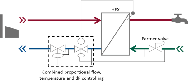
Figure 4. Instantaneous DHW application with a dP controller and thermostatic and proportional DHW controller.
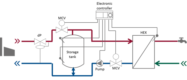
Figure 5. Primary side storage tank and instantaneous DHW preparation.
The difference between the two instantaneous solutions is that if primary side storage tank is applied it is possible to reduce the connection capacity which results in reduced sizes of the service pipes. However, the additional heat loss from the storage tank needs to be considered in connection with the reduced heat loss in the service pipes. Overall the heat loss will in general be lower from the instantaneous solution without the storage tank and the comfort will be higher.
An important factor when it comes to DHW preparation is to limit the waiting time for the hot water. Commonly applied solutions to limit waiting times are: a) minimize the pipe distances and dimensions from the DHW unit to the taps and b) to keep the supply pipe and in some cases the DHW heat exchanger warm during non-tapping periods by using by-passes.
The DHW unit can be kept warm with a by-pass from the supply pipe to the return pipe, by-pass over the control valve or by applying set-back temperatures at the heat exchanger. Figures 6–8 show examples of possible by-pass functions.
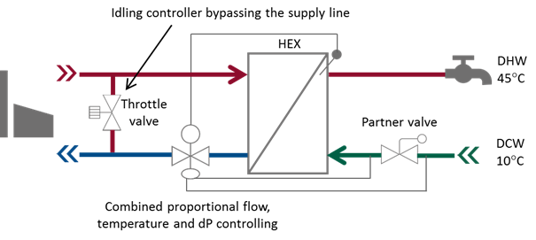
Figure 6. By-pass from the supply to the return line, service pipe kept warm but the heat exchanger kept cold.
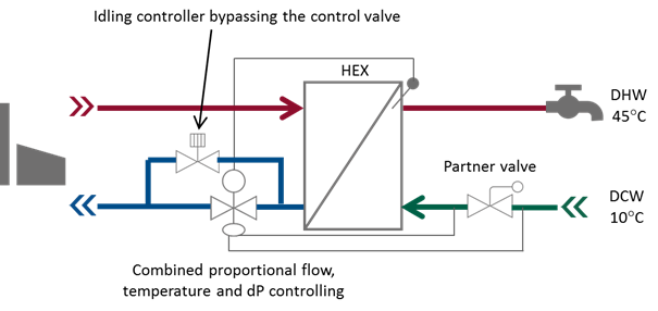
Figure 7. By-pass over the control valve, heat exchanger and service pipe kept warm.
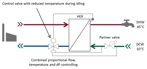
Figure 8. By-pass by applying set-back temperature on the control valve to keep the service pipe and the heat exchanger warm.
The choice of the by-pass function will both impact the waiting time for hot water reaching the tap and the heat loss experienced.
It is well-known that warm water provides favorable conditions for bacterial growth. In hot water systems mainly the Legionella bacteria is considered. Legionella growth is a risk in large volume of standstill water with optimum growth condition at temperatures between 30°C and 45°C.
The approach proposed in relation to LTDH regarding the risk of Legionella is to minimize the DHW installation volume to less than 3 liters and only heat up fresh cold water when taping occurs, i.e. no hot water circulation. With this approach there will be no still standing water as once a taping occurs the existing water volume is completely replaced with new fresh water. In between tapings the hot water in the DHW pipes is allowed to cool down to room temperature.
It is clear that the industry is ready for the 4th generation district heating, low-temperature district heating, and all the necessary technologies are already available.
For existing district heating systems it is important to start already today to specify high performance control equipment and heat exchangers to facilitate the future transition from their current operation to the 4th generation district heating.
By specifying low temperature district heating supply temperatures significant reduction of the heat loss can be achieved, leading to more efficient distribution. Further benefits of reduced supply temperatures are the increased potential to access local low temperature renewable heat sources and increased efficiency of existing heat sources.
The future of district heating as an energy efficient infrastructure is bright and will without doubt play a vital role towards achieving the ambitious goals of limiting the global climate change from human activities.
[1] DWGW Arbeitsblat
W551, Technische Regel, April 2004.
[2] Thorsen, J.E. (2010) Analysis on Flat Station Concept. The 12th International Symposium on District Heating and Cooling, Tallinn, Estonia.
[3] Lund, H. et. al. (2014) 4th Generation District Heating (4GDH). Integrating Smart Thermal Grids into Future Sustainable Energy Systems. Energy Journal, EGY5906.
[4] Brand. M, Svendsen. S, Renewable-based low-temperature district heating for existing buildings in various stages of refurbishment. Energy, 2013.
Follow us on social media accounts to stay up to date with REHVA actualities
0