Stay Informed
Follow us on social media accounts to stay up to date with REHVA actualities

In 2008
Swedish Energy Agency and Statistics Sweden performed a study on hot water use
in single-family-households. This study resulted in, among other things, a user
profile for hot water use presented in Figure 1. The profile shows that the hot
water use is relatively constant during a day except for a time period of 15
minutes when 110 litres of hot water is used [1].
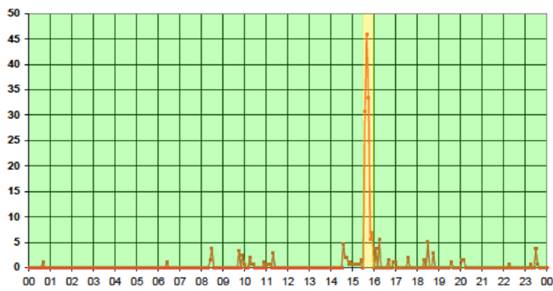
Figure 1
User profile for hot water (Stengård L, Levander T, 2009).
This brings
us to one of the big energy challenges in today’s energy system, to find a
sustainable balance between energy supply and demand. Shifting peak load
through demand side management would be beneficial for the energy system as
this would enable a more even consumption and hence production. This would
further come with economical advantages, as the
electricity price typically is higher at peak load.
One of the
biggest energy consumers in Sweden is space heating including tap water
heating, accounting for 25% of the national energy consumption [2]. The tap
water heating in Sweden is often conducted through a water heater where the
thermal energy is stored through sensible heat storage until demand rises.
However, there are several disadvantages with the sensible heat storage such as
low energy density. This leads to the requirement of a big water heater to
supply enough hot water for a sudden use, e.g. a shower or a bath. A large
storage size does also come with higher thermal losses and larger space
requirement, which can be undesirable.
Sensible heat storage Latent heat storage |
There are
room for improvement and development of the widely used domestic water heater
that could effect the energy
situation both at an individual and on a system level. An opportunity is to combine the
water heater’s sensible heat storage with latent heat storage. The latent heat
storage is considered to be a more efficient and compact storage method. For
example, the phase change of water from solid to liquid require the equal
amount of energy as heating water of the same mass from 0° C to 80°C.
The market
offers a wide range of material for latent heat storage application called
phase change materials (PCM). These have the advantages of isothermal phase
transition, high energy density and can be tailor made for each system to meet
the temperature requirements.
The
proposed system would ideally consist of a small water heater to meet the
average demand during the day combined with a PCM unit to meet the peak load
demand. The PCM unit ought to be charged when demand is low and discharged when
peak arises to shift peak load.
In
practice, hot water from the water heater circulates through the PCM unit
melting the PCM during average load. When peak load occurs the water from the
traditional water heater will drop in temperature and become cold. Cold water
circulates through the PCM unit and thus starting a solidifying process. In
this process the PCM will be discharged, transferring stored energy from the
PCM to the water and thereby heating the tap water.
Schematics
of the described system are presented in figures 2–4. Adopting the proposed system would
enable the water heater to work at a more constant temperature whilst being
able to provide enough hot water at all hours. Thus, a combined water heater
will be smaller, have less losses and work at a lower, constant energy rate.
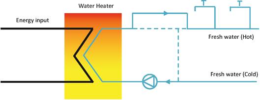
Figure 2.
Uncharged PCM.

Figure 3.
PCM Discharging: Cold water flow through the PCM unit (Fanny Lindberg).
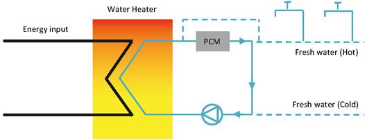
Figure 4.
PCM Charging: Hot water from water heater circulates the PCM unit.
COMSOL
Multiphysics [3] was used to create a model and simulation of the system. The
model created is a development of a verified model created by Justin N.W. Chiu
and Viktoria Martin in 2013 [4]. The user profile in Figure
1 formed the basis
for the simulation. The green area represents the charging and the yellow the
discharging cycle. The system studied is a water heater with a water inlet temperature
of 8,6°C [1] and outlet temperature of 61°C [5]. Place note that the aim for
the combined water heater is to shift peak load (yellow) to the average load
period (green).
Modelling
assumptions of materials ·
Isotropic properties ·
No thermal resistance through surfaces ·
Incompressible fluids ·
Newtonian fluids ·
Adiabatic surfaces facing ambience |
The model
was created as a finned pipe with two times two storage units for the PCM and
is illustrated in Figure 5. When analysed, the model is downscaled to a
two-dimensional axial symmetric module. The biggest challenge in the
development of the model was to create a design with a manageable calculation
time, less than 24 h, but with acceptable accuracy.
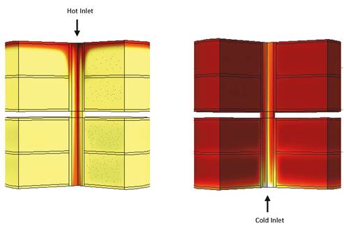
Figure 5
Model in COMSOL Multiphysics.
The finned
pipe material was set to aluminium due to good heat exchanging and
manufacturing properties. The PCM was set to paraffin. It is interesting to
investigate the number of PCM in the energy storage unit and their optimal
phase changing temperature. The driving force for heat transfer is proportional
to the temperature difference. Therefore, it is advantageous to use PCMs with
low phase changing temperature for the charging cycle. The reverse applies for
the discharging cycle. Using a combination of PCMs with varying phase changing
temperatures preserves the driving force. At the same time the water can reach
higher temperatures when discharging and lower when charging. This difference
between single and multi PCM systems is presented in Figure
6a and 6b. The
focus of the study has been to compare PCM units containing one and two PCMs
and to find the most advantageous case for the given application.
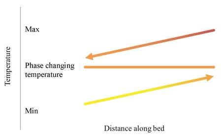
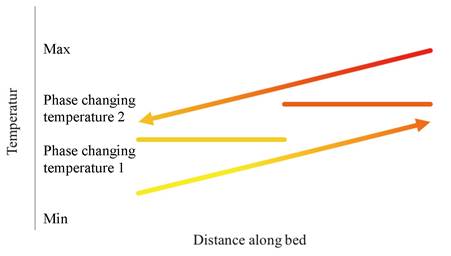
Figure 6a and 6b. Single vs multi PCM heat exchange.
Furthermore,
two temperature zones for phase changing temperatures was studied. One higher
and one lower. To summarize, four cases were studied for the charging and
discharging cycle, respectively. The materials studied in each case are
represented in Table 1.
Table 1
Material composition for each case.
One PCM | Two PCM | |
High phase changing temperature | PCM 50 | PCM42 & PCM60 |
Low phase changing temperature | PCM44 | PCM35 & PCM55 |
The results
of the simulation are presented as the outlet temperature. The outlet
temperature describes the temperature of the water at the outlet of the PCM
unit. The outlet temperature of the water during the charging cycle is
presented in Figure 7. The water temperature at the end of all cases
equals the incoming temperature of 61°C. Thus one can
make the conclusion that all cases provide a fully uploaded PCM unit.
Furthermore, one can conclude that the PCM units holding two PCM materials
provide a faster charging as the maximum temperature is reached faster. Hence,
the system engineering challenge lies in the discharging cycle.
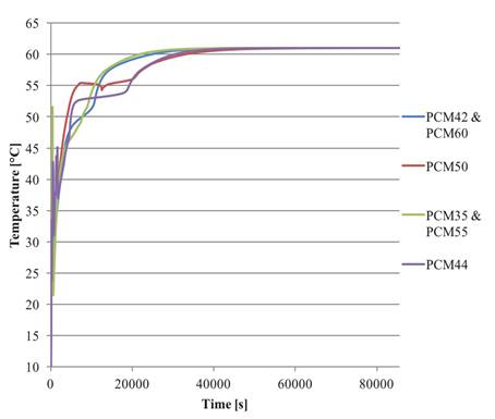
Figure 7.
Outlet temperature of water, charging cycle.
The outlet
temperature of the water for the discharging cycle is presented in Figure 8.
The outlet temperature is lower than the desired one for all cases at all
times. However, the inlet temperature is elevated by 15-26°C. Figure 8 presents
that the highest outlet temperature is reached for the case of high phase
changing temperature and two PCM. The difference between one and two PCM are,
however, not significant. To reach an even higher outlet temperature a higher
working temperature would be eligible. The system could be further developed if
multiple devices were in series or in parallel. This would provide a larger
area for heat transfer and a longer contact time which would increase the heat
transfer and thus the outlet temperature.
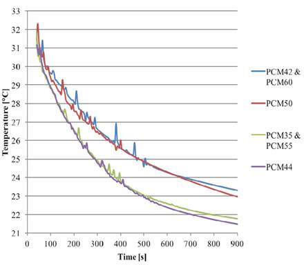
Figure 8.
Outlet temperature of water, discharging cycle.
The
recommended system for the given application would contain PCM with high phase
changing temperature. The charging cycle exhibits full charge for all cases
whereas the discharge cycle is critical. For the discharge cycle a sufficiently
high outlet temperature is not reached with the developed model. However, a
significant rise in temperature from 8.6°C is achieved. The PCM unit with two
PCMs provide a slightly higher temperature but more detailed studies of
multiple user profiles with a design reassessment should be done to determine
which case is most advantageous. It is clear that the system is applicable and
feasible in theory, as it allows a shift of the load.
Further
studies concerning the possibility of connecting devices in series should be
done in order to investigate the circumstances under which higher outlet
temperatures can be reached. To summarize, performance improvements can be
reached using multi PCM. However, the question whether this is sufficient to
outweigh the possible design and construction complications remains.
[1] Stengård L, Levander T (2009), Mätning av
kall- och varmvattenanvändning i 44 hushåll, Energimyndigheten, Eskilstuna,
Sweden
[2] Persson T (2000), Lågtemperaturvärmesystem,
Högskolan i Dalarna, EKOS, Borlänge, Swe-den
[3] COMSOL Multiphysics 5.0, Copyright 1995-2006
Mort Bay Consulting Pty Ltd
[4] Justin N.W. Chiu, Viktoria Martin (2013),
Multistage latent heat cold thermal energy storage design analysis, Royal
Institute of Technology, KTH, Department of Energy Technology, Stockholm,
Sweden
[5] Boverket (2015),
6:6 Vattenochavlopp, available at http://www.boverket.se, read
2015-02-23
Follow us on social media accounts to stay up to date with REHVA actualities
0