


Stay Informed
Follow us on social media accounts to stay up to date with REHVA actualities
|
|
|
Jiří Dostál | Tomáš Bäumelt | Jiří Cvrček |
Czech Technical University in Prague, University Centre for Energy Efficient Buildings, Buštěhrad, The Czech RepublicCorresponding author: jiri.dostal@cvut.cz | ||
This article focuses on one-pipe hydronic networks, also called single-pipe or referred to as primary-secondary pumping systems. Nowadays, however, mostly two-pipe hydronic heating systems are used. The most widespread is quantitative control, where varying hydraulic resistance in a branch controls flow through a heat terminal. The easiest quantitative control actuator is a manual valve; however, nowadays, legislative norms (e.g. [1]) no longer allow its use. At least automatic thermostatic valves have to be utilized. A thermostatic valve controls its opening mechanically, depending on the room temperature. A more up-to-date solution is the use of Pressure Independent Control Valves (PICV, [1]), which are utilized mostly in fan-coil unit (FCU) applications. A PICV contains a spring mechanism for maintaining a constant pressure drop across an adjacent control valve; the flow, therefore, depends only on the valve opening and not on any pressure variations [1].
Another way to control a hydronic system is to pump heat transfer liquid where needed instead of throttling it where not required. This solution is already available on the market [2,3] and uses a small pump for each heat terminal. Let us call systems with throttling valves “passive” or “throttling” and systems using the pumps “active” or “pumping”. Wilo AG has also established a terminology where throttling systems are called “supply oriented” and those with pumps “demand oriented”. It is also possible to meet the term “centralized” for systems with a central pump and “decentralized” for decentralized pumping systems.
Although there is also a two-pipe variant of a decentralized pumping system [2,4], this article expands only on the one-pipe pumping hydronic network and its designated control device.
The article presents a pumping one-pipe network and the control device development, algorithms and real-life validation.
Pumping one-pipe systems, also referred to as “primary-secondary pumping” [5], are mostly used to connect heat sources but can also be utilized on the load side. In short, from the main pipe in a circuit branch out two closely-spaced T-fitting to where a secondary (the “small”) pump with a heat source/terminal is looped in. The heat sources/terminals are connected in series on the main (primary) piping. The main piping loops from, say, heat load to a main circulator, heat source (or hydraulic separator) and back to the heat load. See Figure 1 for a schematic depiction.
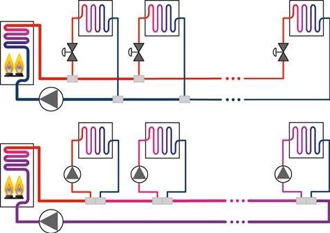
Figure 1. Hydronic topologies: two-pipe throttling system (top), pumping one-pipe system (bottom).
The advantages of the pumping one-pipe hydronic system are:
· the system generally contains only two pipe diameters (primary and secondary),
· time and material savings (fewer pipes, connections, valves and plumber's work),
· one type of pump in the secondary loop can control a wide range of load capacities; i.e. the system is robust against design inaccuracies/changes,
· the amount of the overall dissipated pumping energy is the lowest of all possible topologies,
· one-pipe system contains less heat transfer liquid (water, glycol) than a comparable two-pipe system.
The disadvantages are:
· practitioners mostly hold the impression that one-pipe systems are inefficient and problematic. This is based on the long-surpassed throttling one-pipe heating variant with its real higher operational cost and low comfort [5]. It harms, beforehand, the reputation of pumping one-pipe systems,
· temperature relations among secondary loops shall be considered during system design. There is a one-pipe network design and validation tool [8,9] available. But solutions for retrofitting two-pipe systems also exist,
· this solution became feasible only recently as canned wet rotor pumps, and electronically commutated motor became available. There are not many installations proving the performance of the system. Despite that, dozens of pumping one-pipe systems are in service in the US, e.g. [3].
For more hydronic network topologies details and a one-pipe network design tool description, resort to [6].
The speed of the secondary pump controls the power output of a heat terminal in the pumping one-pipe network. And as there is no variable hydraulic resistance in the secondary circuit, the secondary flow is governed solely by this speed.
Such conditions enable us to infer flow from pump power readings, as Figure 2 depicts. Knowing the pump speed, power, and power-flow characteristics is the main predisposition to estimate the absolute volumetric/mass flow through the pump and consequently through the whole secondary circuit, i.e. the heat terminal. A heating/cooling power can be calculated by adding a pair of temperature sensors on a supply and return secondary pipe.
Our patented invention [7,8], with the business name Q-pump (Qp), bundles the two closely-spaced T-fittings, a pump housing, a check-valve and a pair of temperature sensors together into one device. Such a device directly connects a heat source/terminal to the main pipe. See Figure 3 for a schematic depiction.
Note: Although the same principles generally apply to heat sources, the one-pipe control pump devices will only be depicted in the heat distribution to the heat terminals. Also, even though only heating will be addressed further, similar principles apply to the distribution of cooling power.
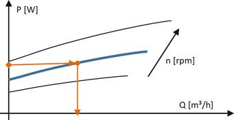
Figure 2. The basic principle of inferring flow from a pump electrical power reading.
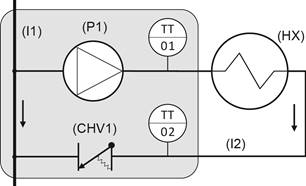
Figure 3. One-pipe control pump device scheme. HX – heat exchanger, CHV – check-valve, I – pipe, P – pump, TT – temperature sensor.
The EU directive [9] recommends designing heat sources for a typical building load (instead of a maximal load), with a complimentary heat source to cover for extreme conditions. Applying the same principle to heat distribution, the main pipe has been chosen DN32 with G5/4 threads, which renders an economic pressure drop [10] for supplying one floor of 75% of commercial buildings in the EU [11]. The other 25% of establishments with higher loads shall, but only for 6% of operation time [12], experience higher main pipe velocities than 1.2 m/s and, therefore, higher pressure losses.
The device's secondary piping and pump are sized for a load of 10 kW with an average weighted hydraulic conductivity of 0.8 bar/m³/h. The secondary ports are DN15 with G1/2 threads, the standard connection for most heat terminals. See Figure 4 for results from the research on typical design operation conditions (normalized using EN 442-1:1995) and specific loads.
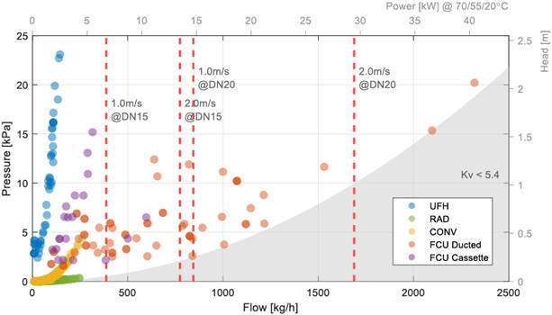
Figure 4. Typical design operation conditions for underfloor heating (UHF), radiators (RAD), convectors (CONV) and fan-coil units (FCU). All datasheet values normalized to conditions 70/55/20°C using the norm EN 442-1:1995.
A D5-sized pump [13] (used in, for example, solar-thermic installation or hot water recirculators) serves as the secondary pump. It is a spherical-shaped wet-rotor electronically commutated pump with four rotor poles and six stator coils on a magnetic core ring.
The Qp body (Figure 5) consists of the main pipe, from which a pump housing extends with its suction hole. The pump outlet directs perpendicularly away from the main pipe axis. The secondary outlet port houses a spring check valve and a secondary supply temperature sensor. From the same direction comes the secondary inlet, where the secondary return temperature sensor is housed and which connects back to the main pipe.
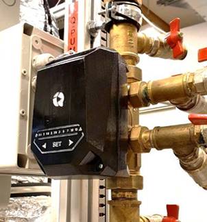
Figure 5. One-pipe control pump device: brass-casted and machined body with injection-mould-manufacturable electronics cover.
The Qp body was made as symmetrical as possible from the primary-pipe point of view to enable directing the secondary ports to the right or left regardless of the flow direction in the main pipe. Which means that the direction of flow in the main pipe does not alter hydraulic conditions in the secondary piping.
The first prototypes were manufactured using 3D printing. The final prototypes are cast from brass using ceramic moulds (created on top of 3D printed masters). The final body design is fully brass-castable and machinable by standard machining techniques.
The electronics cover is designed to be injection-moulded without any special cores. It is designed to comply with IP44 and cable-pull protection.
The electronics utilizes an NXP i.MX-RT microcontroller with built-in motor control features. The pump speed and electrical power acquisition are performed by vector control methods (FOC) [14], allowing for efficient device control in the whole range from zero to maximal flow.
The processor runs FreeRTOS and allows for temperature readings, heat power estimation, controller calculations and communications.
Mass flow estimation is the key component of the one-pipe control pump device. Being able to determine flow without the use of a flow meter enables cost-effective implementation of the following features:
· Heat flow estimation
· Heat flow control
· Heat metering
· Thermal diagnostics
Looking at the schematic of the secondary circuit (Figure 3), there are three main features from the hydraulic point of view: the double T-fitting (connection to the primary circuit), the pump body with a check-valve and the hydraulic load - the heat terminal with its piping. The T-fittings are spaced closely together not to create a pressure source for the secondary circuit. Changes in the primary flow do not influence the secondary flow (verified by measurement, variation is less than 5 ℓ/h per 1000 ℓ/h change in the primary flow) – hence the two circuits are hydraulically separated. This simplifies the secondary hydraulic circuit to just two components: the pump and the load.
The Qp device sizing doesn't change up or down with the capacity of the load; the control authority is always full, as we control the flow directly. Precision speed control of the pump means sufficient flow control precision for any load capacity. Therefore, the QP body, with its pump housing, check valve and ports, is of a fixed size and can be described precisely by its head-flow (HQ) and power-flow (PQ) characteristics. Figure 6 presents the measured data and the polynomial model. Fitting was performed under an L1 norm with shape constraints [15].
Mass flow estimation is based on the underlying mathematical model of the circuit (Figure 7), the fixed but unknown hydraulic load and the fixed and known pump with its housing.
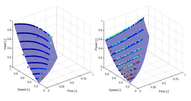
Figure 6. the Qp device characteristics fitting for HQ plane (left) and PQ plane (right).
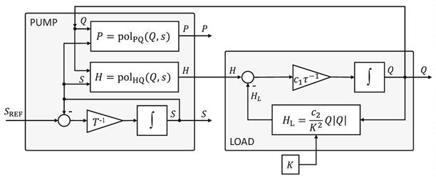
Figure 7. Simplified scheme of the dynamical model used for mass flow estimation.
The pump model is mainly given by the head and power polynomials; partial effects have the inlet water and motor coil temperature. The dynamic behaviour is primarily governed by the speed controller, flow inertia and impeller inertia. The latter ones are, however, fast enough to enable coarse approximation by first-order dynamics.
The quadratic Darcy-Weisbach law mainly gives the model of the load. The hydraulic conductivity is unknown but considered only very slowly changing. The dynamical flow model is derived from an analogous inertance model, where the head difference between input and load is the flow change driving potential. The hydraulic conductivity Kis mildly dependent on mean water temperature.
The model is non-linear, with one parameter
and two states to be estimated. The states, pump speed S and
most importantly, the flow Q, altogether with the hyd. conductance of the load K are
estimated by an extended Kalman filter (EKF). The resulting flow is denoted ![]() .
.
A heat terminal, e.g. FCU, is generally a distributed parameter and distributed time-delay system governed, when simplified, by a one-dimensional hyperbolic PDE [16]. Additionally, temperature measurements are situated at the Qp device, so there is a possibly significant transport delay due to the secondary piping length.
Standard PID feedback control is not suitable for such a system. However, a controller by Sandoval [17] is specifically designed for robust velocity control of convective spatially distributed systems, e.g. heat terminals.
The control problem statement is to find a controller that drives the heat control error e to zero.
The stabilizing control law is defined as
Where sg(e) = 1 for e ≥ 0 and sg(e) = −1 otherwise. | (1) |
The two constants kP and kI are tuning parameters for proportional and integral action, respectively. The controller can be considered a PI controller with a variable integral gain. An anti-windup modification has been utilized to prevent wind-up situations.
In our scenario, the heat control error is given as
where cp [J/kg/K] is the specific heat capacity of the heat transport fluid (assumed water, a statistical test for the presence of water can be performed), Twi and Two [°C] are supply and return temperature measurements in the Qp device. Heat flow reference QREF [W] is given by a supervisory temperature controller – a wall module or a zone temperature MPC [18]. | (2) |
The development of the Qp device would not be possible without a precise and multifunctional testbed.
The hydronic testbed for hydronic control devices with temperature feedback (Figure 8) contains three connected circuits.
The primary hydronic circuit starts with the main pump and passes through a hot-water tank, the primary side of the Qp device, set of PT1000 temp. sensors and electromagnetic flowmeter routes back to the primary pump.
The secondary circuit starts at the Qp device secondary ports and passes through an actuated valve, a Coriolis flowmeter, a set of PT1000 temp. sensors to a water-to-air heat exchanger and back to the Qp device. A precise differential pressure sensor connects to the Qp ports on the secondary or the primary side.
An airstream starts with a straight duct with a Wilson grid flowmeter and continues through a controlled fan and a set of PT1000 temp. sensors into the water-to-air heat exchanger, from where it leaves the testbed.
The testbed also contains a small tank holding water of significantly different temperature to realize sharp temperature changes. It connects to the primary pipe via an old Qp prototype.
An ADRC controller controls the heating tank, and airflow and primary water flow are controlled by regular PI controllers. See Figure 8 for a depiction of the testbed.
Two-pipe throttling actuators with temperature feedback may also be developed/tested here.
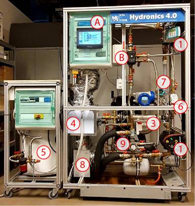
Figure 8. Hydronic Testbed. A) testbed controller, B) one-pipe control pump device, 1) primary pump, 2) primary induction flowmeter, 3) secondary Coriolis flowmeter, 4) water-to-air heat exchanger, 5) main tank, 6) actuated valve, 7) differential pressure sensor, 8) controlled fan, 9) second tank for sudden temperature changes.
Figure 9 presents flow estimation precision. The data were obtained by ramping the pump speed up and down, preceded by three load steps, where the EKF identified the hydraulic load. The actuated valve connected to the secondary circuit was randomly positioned to represent an unknown hydraulic load. The standard deviation in the whole range for the actual hydraulic load is 3.91 ℓ/h; however, the estimation in the low-flow region is not entirely accurate due to the lack of feedback from the pump's electrical power reading, as the PQ characteristic is flat here.
Figure 10 presents the heat flow control of the water-to-air heat exchanger. The results were obtained by ramping up and down the absolute heat reference value. The standard deviation over the whole range of the heat terminal was 158 W. However, the tracking precision at low heat flows is not very satisfactory due to multiple factors.
First and foremost, the error in mass flow estimation is a factor. Second, the delivered (real) heat is calculated from wet-well water temperature sensors positioned directly on the heat exchanger inlet and outlet. In contrast, the estimated power is calculated from dry-well temperature sensors onboard the Qp device, and there is a good portion of uninsulated piping in between. Note that the heat flow controller always tracks the heat estimate exactly to the reference, but the estimated power differs from the real one. The systematic power control error in the higher flows is likely due to the heat dissipated by secondary piping (not insulated) and other errors in temperature measurements; the flow estimation error adds up to the latter in the low flow region.
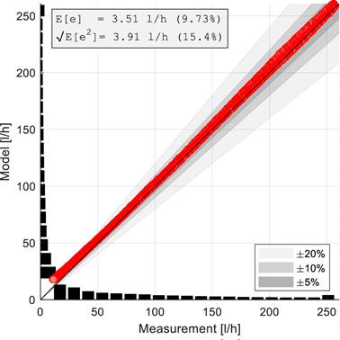
Figure 9. Flow estimation precision for a random fixed position of the actuated valve in the secondary circuit.
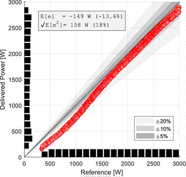
Figure 10. Steady-state heat flow control precision for the heat terminal present at the hydronic testbed.
This paper presents the results of a three-year-long development of the one-pipe control pump device: a Q-pump. We have built a well-working testbed suitable for developing temperature feedback hydronic actuators (valves, pumps) and have designed and built the Qp device according to the patented ideas. The paper presents the mechanical development process and the core working principle from the estimation and control point of view. Measurements validate the method to be sound, although there is still room for improvement in details. Future development will be directed towards thermal diagnostics, mainly detecting diminishing heat transfer due to dust build-up in an FCU.
This research was funded by the Technology Agency of the Czech Republic, grant number TK01020024.
Please find the full list of references in the original article at: https://proceedings.open.tudelft.nl/clima2022/article/view/349
Follow us on social media accounts to stay up to date with REHVA actualities
0