

Stay Informed
Follow us on social media accounts to stay up to date with REHVA actualities
Jiří PetrákCSc. prof. Ing.CTU in Prague, Faculty of Mechanical
Engineering, Department of Power Engineering | Miroslav PetrákPh.D. doc. Ing.CTU in Prague, Faculty of Mechanical
Engineering, Department of Power Engineeringmiroslav.petrak@fs.cvut.cz |
The heat
pump and the heating system (hereinafter referred to as the HP and the HS) are
two separate units with different characteristics. The lower the outside air
temperature, the higher the heating system demands on the heat, both on its
quantity and the temperature level. For a long time, only heat pumps with
constant compressor speed depended on the frequency of the electrical grid 50
or 60 Hz were available, where the HP regulation according to the needs of
the heating system was solved by the jumping system on / off. The shortage of
heating capacity below the bivalent temperature is covered by an additional
heat source, very often an electric boiler. Excess heat has to be accumulated
in heating water, whose temperature than rises above the required heating
system inlet temperature.
An example
of the capacity and temperature relationship in the HS during the heating
period is shown in the graphs of Figures 1–4. The graphs are processed for the
average climate conditions according to EN 14825 (minimal ambient
temperature −10°C, maximal 16°C), objects with two nominal heat loss of
20 kW and 30 kW, two heating systems represented by a low-temperature
one of 35/30°C and a high-temperature one of 55/47°C and the HP with
refrigerant R410A. The figures on the left refer to the HP with the constant
speed compressor ZH15K1P-TFM of displacement of 11.7 m³/h (heating
capacity 16.8 kW at A2/W35), the figures on the right refer to the
variable speed compressor ZPV0631E-4E9 of displacement of 11.0 m³/h (at 50 Hz).
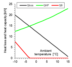
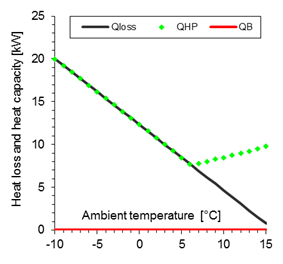
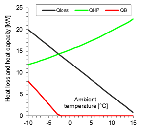
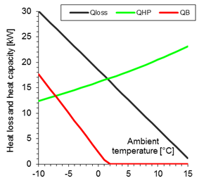
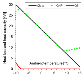
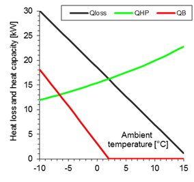
The monitored quantities are indicated in the figures as follows:
Qloss | thermal loss of the building in kW |
QHP | heating capacity of the HP in kW |
QB | heating output of electric boiler in kW |
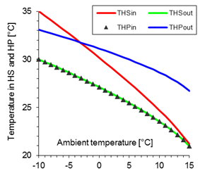
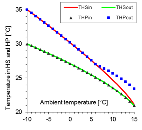
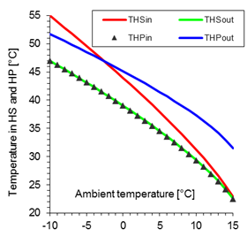
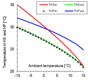
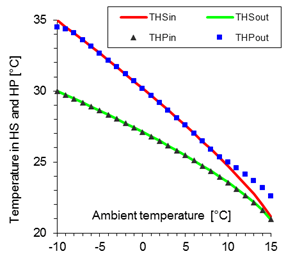
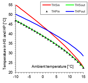
THSin | water temperature at the inlet to the HS |
THSout | water temperature at the HS outlet |
THPin | water temperature at the inlet to the HP |
THPout | water temperature at the HP outlet |
If a
constant speed HP with the previous mentioned compressor size is used in an
object with a nominal heat loss of 20 kW and a low-temperature heating
system of 35/30°C (Figure 1, left), it results a bivalent
operation (bivalent parallel) with the balance point determined by capacity.
The balance point temperature is about −3°C and besides the HP, a
bivalent heat source with a capacity of up to about 7.5 kW for ambient
temperatures of −10°C is required.
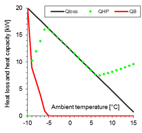
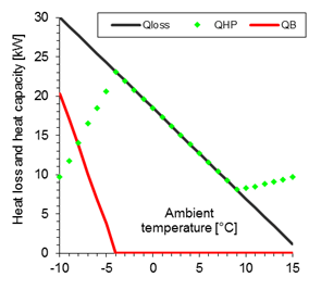
If a
variable speed compressor is used, it operates in the frequency range of 20 Hz
to 85 Hz and, therefore, still has a capacity reserve, since the maximum
frequency is 120 Hz. It can be seen that the temperature of the water
leaving the HP exceeds the required inlet temperature to the HS only at ambient
temperatures over 6°C because the compressor cannot operate at a frequency
below 20 Hz to reduce the heating capacity to the desired HS value. The
system can be rated as monovalent.
|
|
|
|
|
|
|
|
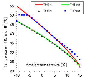
If the
high-temperature heating system 55/47°C was used in this object, the operating
conditions would correspond to the state shown in Figure 2. A significant change will occur in
the HS with an HP with a variable speed generator, where the system converts
from monovalent into bivalent - partially parallel. With outdoor air
temperatures below −5°C, the heat pump still has sufficient heating
capacity (the compressor frequency is only about 59 Hz), but it cannot
heat the water to the desired HS temperature because the condensing temperature
would go beyond the compressor's operating limits. In order not to exceed the
maximum allowable condensing temperature, the compressor speed is gradually
reduced at outdoor temperatures of approx. −5°C to −9°C, but the
compressor’s operating range decreases significantly, especially at speed below
40 Hz (see Figure 5), so at the ambient temperature
below −9°C, the compressor should be switched off. This is reflected,
among other things, by the need to dimension a bivalent heat source to the full
nominal object’s heat loss.
In Figures 3 and 4, these heat pumps are monitored when used in an object with a nominal
heat loss of 30 kW, where the constant speed of the compressor reaches the
balance point temperature at +2°C. This temperature is specified in the
ČSN EN 14825 and Commission Regulations (EU) No. 811/2013 and
813/2013 as the maximum balance point temperature for the average climate
conditions. This size of the heat pump with a compressor ZH15 compressor with
constant speed is suitable for objects in the average climatic area up to this
nominal heat loss. Therefore, the behaviour of the heat pump is not monitored
in buildings with a higher nominal heat loss than 30 kW in this paper.
|
|
|
|
|
|
|
|
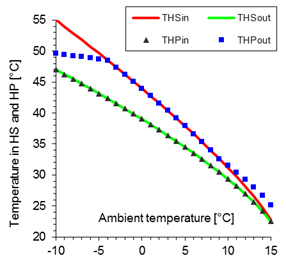
Figure 4. High-temperature heating system
of 55/47°C, heat loss of the building of 30 kW (constant speed
compressor on the left, variable speed compressor on the right). | |
It is
important to note that the HP with a variable speed compressor in the HS of
55/47°C with a nominal heat loss of 20 kW (Figure 2) could no longer work at the
ambient temperature of −10°C, in that with a heat loss of 30 kW, it
works properly with a heating capacity of about 9.7 kW. This is due to the
fact that, when demanding higher capacity, it operates at higher speed
corresponding to a wider operating range.
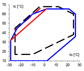
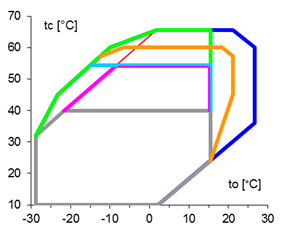
In Figure 5, the operating areas of both compressors are specified for refrigerant
R410A, depending on the evaporation temperature to and the condensation tc. For the cooperation of variable
speed compressors with a high temperature HS (e.g. the observed 55/47°C), the
slightly lower condensation temperature compared to the fix speed compressor
and the reduction of the operating area at high or low frequencies as shown in
the right part of Figure 5 are unfavourable.
|
|
Figure 5. The operating
zone of the employed compressors (valid for overheating at the inlet at 5K;
the zone is limited by red line for overheating at 10 K): dashed line for the
ZH15K1P-TFM compressor with constant speed; solid line for the ZPV0631E-4E9
compressor with variable speed (dark blue 43 Hz to 100 Hz, grey 20 Hz,
purple 30 Hz, green 40 Hz, orange 110 Hz, light blue 120 Hz). | |
For
effectiveness description, the Coefficient Of Performance (COP) is used as the
ratio of heating capacity to the input power. Today, ČSN EN 14825
defines a total of 8 types of numerals that distinguish between the indices
with the abbreviation COP or (if associated with a certain
period of time) it has the SCOP designation and specifying the
added index if it is only for the HP (then SCOPnet) or includes the power consumption by an
additional source (SCOPon). At the
same time, for the purposes of calculating the reference SCOP, three reference climate conditions are established: average, warmer
and cooler. For these conditions, the range of ambient temperatures and the
corresponding heating hours are given. The heating period in all three
condition types uniformly ends at an outdoor air ambient temperature of 16°C.
Climate
conditions in the Czech Republic are best reflected by the average climate
conditions [5]. Therefore, they were used in the calculation of SCOPon values and for the determination of
the annual energy savings. For simplification, this is understood as the
difference between the thermal energy delivered to the HS and the electricity
required for the operation of the compressor and an electric heater as the
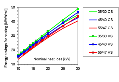
additional bivalent heat source. Results are shown in Figures 6 and 7 for the assumed use of the heat pump in buildings with a nominal heat
loss of 10 kW to 30 kW where COP also reaches their maximum.
A large
heat pump in a building with a low heat loss means a large investment cost, but
according to Figure 7, has a small energy saving, i.e., a
long payback period. Besides that, there is also a risk for a variable speed
compressor in high-temperature heating systems that the low compressor speed
restricts the permissible operating limits below temperatures required by
heating system, so the heat pump cannot be operated for a major part of the
heating period although it is oversized. This is the reason for the missing
data of around 10-11 kW for heating the system of 55/47°C in Figures 6 and 7. It is, therefore, necessary to install a heat pump of appropriate
capacity relative to the size of the object and to operate it at the higher
speed of the compressor.
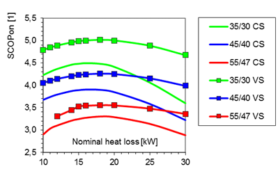
Figure 6. Seasonal Coefficient of
Performance SCOPon for different
heating systems: CS – constant speed compressor; VS – variable speed compressor.
Although,
in Figures 1–4, a heat pump with a variable speed compressor
better follows the needs of the heating system, the improvement of the seasonal
SCOPon is only about 10% relative to a
compressor with a constant speed in buildings with a heat loss of 15 kW to
about 22 kW (for a heating system of 55/47°C, approx. 8% only). The
explanation can be found in the weaknesses of the variable speed compressor,
namely its working area (see Figure 5), as well as the higher energy
demand of its operation, which is illustrated in Figure 8 by comparing the specific
compression work based on the manufacturer’s data shown.
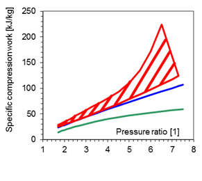
Figure 8. Specific compression work in dependence on the discharge
to inlet pressure ratio for the isentropic compression (green) and for the
ZH15K1P-TFM (blue) and the ZPV0631E-4E9 (red; hatched area
for permissible speed range) compressors
It should
be noted that Figure 8 does not compare the parameters of
the HP, but only the compressors. For a variable speed compressor, this
variable also depends on the frequency and its values fill the area defined in
the figure with red lines.
In
buildings with a nominal heat loss of above approx. 22 kW, the SCOPon of a given heat pump with a
constant speed compressor is continuously decreasing. This is due to the
gradual increase in the balance point temperature and, hence, the longer
operation of the bivalent heat source of higher capacity. On the contrary, a
heat pump with a variable speed compressor can increase the capacity due to a
higher frequency and has a flatter characteristic of the seasonal SCOPon, which can be up to 16% till 30%
higher than the constant-speed heat pump of the same performance. To improve
the heating factor of a constant speed compressor system in such large
buildings, it would be necessary to choose a higher performance compressor.
In this
paper, heat pumps differing only from compressors (constant speeds and variable
speeds varying in the range of 20 to 120 Hz, but approximately equal
displacement of 11.7 and 11.0 m³/h at 50 Hz) were compared. The heat
exchangers were identical in both designs (with the same characteristics). Any
heat losses due to the heat accumulation have not been considered. This may, in
fact, handicap the variant with a constant speed compressor, as the heat
accumulation often occurs.
For objects
with a nominal heat loss of about 15 kW to 22 kW, a heat pump with
variable speed can achieve a better seasonal SCOPon by about 10%. In those of 30 kW, this can
even be by 16 to 30% depending on the heating system. Due to the increase of
the heating capacity by increasing the speed, a heat pump with a compressor of
a similar displacement (at 50 Hz) can cover larger objects, but smaller
objects (due to the compressor size) may have problems in connection with the
significant reduction of the working range (especially heating systems with
high water temperatures). A smaller variable speed compressor (with smaller
displacement) than for a heat pump with a constant speed compressor will
suffice for such an object.
The authors
wish to thank doc. Ing. Tomáš Matuška, Ph.D., for reviewing the article.
[1] ČSN EN 14825 – Klimatizátory
vzduchu, jednotky pro chlazení kapalin a tepelná čerpadla s elektricky
poháněnými kompresory pro ohřívání a chlazení prostoru – Zkoušení a
klasifikace za podmínek částečného zatížení a výpočet při
sezónním nasazení.(Air conditioners, liquid chilling packages and heat pumps, with
electrically driven compressors, for space heating and cooling - Testing and
rating at part load conditions and calculation of seasonal performance.) ÚNMZ, 2014.
[2] Commission Regulation (EU) No 811/2013 of 18
February 2013 supplementing Directive 2010/30/EU of the European Parliament and
of the Council as regards the indication of energy labelling of heater for
domestic heating space heaters, combined heaters, sets consisting of a heater
for indoor heating, a temperature controller and a solar system, and sets
consisting of a combined heater, a temperature controller and a solar system.
Official Journal of the European Union L 239, p. 1-82 of 6 September 2013.
[3] Commission Regulation (EU) No 813/2013 of 2
August 2013 implementing Directive 2009/125/EC of the European Parliament and
of the Council with regard to eco-design requirements for indoor heaters and
combined heaters. Official Journal of the European Union L 239, pp. 136-161 of
6 September 2013.
[4] Design Software by Copeland: Select, version
7.13.
[5] PETRÁK, J., KOLOVRATNÍK, M.,
PETRÁK, M. Teplota vzduchu v otopném období z pohledu legislativy. (The Air Temperature in the Heating Season in
Terms of Legislation). Vytápění, větrání, instalace (Journal of Heating, Ventilation and Sanitary Installation) 3/2017, pages 144–148. ISSN
1210-1389.
Follow us on social media accounts to stay up to date with REHVA actualities
0