
Stay Informed
Follow us on social media accounts to stay up to date with REHVA actualities
|
Rafał Polichnowski |
Sales DirectorSmaywww.smay.eu |
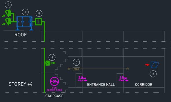
In this article, we will focus on the class B pressure differential system and the airflow rate criterion, that is the air supplied to a zone engulfed in fire, which is 2 m/s (Figure 1). The airflow rate must be ensured at an open door in a baffle between the zone engulfed in fire and protected space (an entrance hall or a lift foyer).
This criterion can be met by supplying an adequate quantity of air to the stairwell, and then forcing it through an open door to the entrance hall and the zone engulfed in fire, or by first supplying air directly to the entrance hall, and then to the zone engulfed in fire. Before we decide on a place to supply air in order to meet the airflow rate criterion of 2 m/s, we should conduct an architectural building analysis and an airflow dynamics analysis between the place where air is supplied and the place where it is extracted.
Let’s assume that the doorway, for which the airflow rate is measured, has an area of 2 m². The quantity of air that should be supplied is then 2 m² × 2 m/s × 3 600 = 14 400 m³/h. It is important to know that the air will only flow from the overpressure zone if the room engulfed in fire has an appropriate exhaust located outside the building. If there is no exhaust, the pressure between the zones will be equalized, resulting in a dynamic migration of smoky air to the protected zone (i.e. the staircase /lift foyer /entrance hall).
Let’s first agree with the architect on a solution to extract hot smoke from the zone engulfed in fire (mechanical or gravitational). The extraction value must be equal or greater than 14 400 m³/h.
Today, we are going to discuss solutions using gravitational extraction of hot smoke from a zone engulfed in fire.
When using this solution, we need to ensure the lowest possible calculated airflow resistance as the resistance value directly impacts the entire pressure differential system output. In the class B pressure differential systems, with an airflow rate of 2 m/s at the staircase the door is open not only at the storey engulfed in fire, but also below this storey and at the storey where evacuation from the building takes place (usually the ground floor).
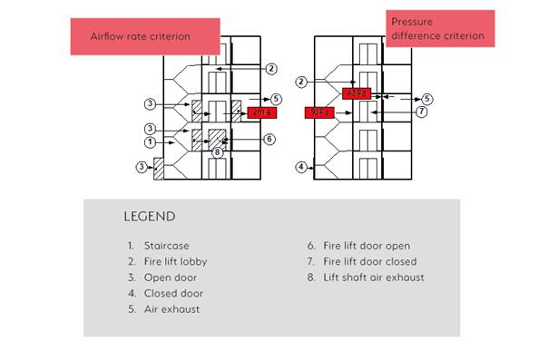
Figure 1. Requirements for positive pressure differential system Class B.
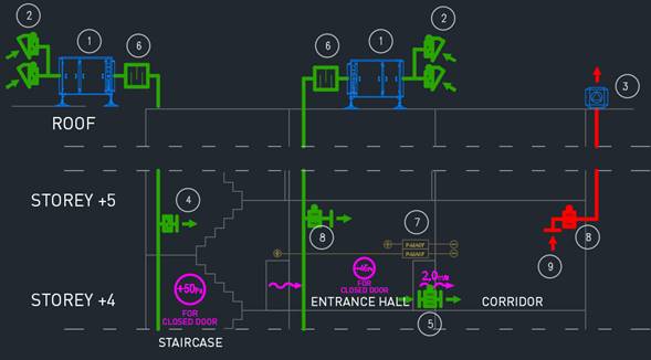
a) Let’s assume that the entire air is supplied to the staircase (Figure 2). The air flowing at a rate of 14 400 m³/h passes through the doorway between the staircase and entrance hall, and then through the doorway between the entrance hall and the zone engulfed in fire. Subsequently, the air is pushed out of the building through the provided exhaust. Let’s analyse the resistance and system output generated with this airflow criterion.
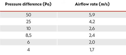
The air flowing through the doorway from one zone to the other at a rate of 2 m/s generates a resistance of 6 Pa (Table 1). We have two doorways. The total resistance equals 12 Pa. Next, let’s assume that the air will be extracted through a smoke exhaust window. It has an area of 2 m². The total resistance thus amounts to 18 Pa. We can therefore state that all the other openings in the staircase require a resistance of at least 18 Pa so that the air passes through an open door in the direction of the smoke exhaust window.
Table 1. The rate of air flowing through gaps or bigger openings.
The biggest opening in the staircase is an open emergency exit door outside the building. Let’s assume that its area is 2 m². In order to ensure a flow resistance of 18 Pa, the airflow rate must equal 3.5 m/s. It seems that – considering that the air should flow to the staircase at a rate of 2 m/s – we must supply additional 25 200 m³/h (we shall not include any other leaks in the staircase in this analysis). Therefore, the total amount of air required to meet the airflow rate criterion with such a gravitational exhaust is 14 400 m³/h + 25 200 m³/h = 39 600 m³/h.
|
Figure 2. Air inflow into the stairwell. |
1. Pressure differential systems unit, the iSWAY air supply unit 2. Damper-controlled double supply louvre system 3. Remote pressure sensor 4. Air supply grille with a damper 5. Smoke exhaust window with an actuator – exhaust feature 6. Acoustic silencer |
Now, we should consider a proper placement of air supply points in the staircase in order not to exceed door opening force at any storey, i.e. 100 N.
ATTENTION! In case of the pressure difference criterion leaks in the staircase may be significantly lower (Figure 1). The fan must therefore supply extremely different quantities of air depending on the number of open and closed doors. Only devices with valid certificates stating fan working ranges and system response times should be used.
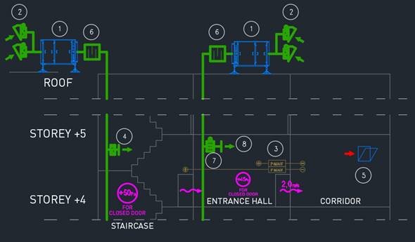
b) Let’s assume that the entire air is supplied to the entrance hall (Figure 3). The air flowing at a rate of 14 400 m³/h passes through the doorway between the entrance hall and the zone engulfed in fire. Subsequently, the air is pushed out of the building through the provided exhaust. Let’s analyse the resistance and system output generated with this airflow criterion.
|
Figure 3. Air flowing through a doorway. |
1. Pressure differential systems unit, the iSWAY air supply unit 2. Damper-controlled double supply louvre system 3. P-MACF remote pressure sensor 4. STW/GA air supply grille with a damper 5. Smoke exhaust window with an actuator – exhaust feature 6. TAP rectangular acoustic silencer 7. KWP-P-E fire ventilation damper with an actuator 8. STW air supply grille |
The air flowing through the doorway from one zone to the other at a rate of 2 m/s generates a resistance of 6 Pa (Table 1). We only have one doorway, so the total resistance is 6 Pa. Next, let’s assume that the air will be extracted through a smoke exhaust window. It has an area of 2 m².
The total resistance thus amounts to 12 Pa. We can therefore state that all the openings in the staircase require a resistance of at least 12 Pa so that the air passes through an open door in the direction of the smoke exhaust window.
The biggest opening in the staircase is an open emergency exit door outside the building. Let’s assume that its area is 2 m². In order to ensure a flow resistance of 12 Pa, the airflow rate must equal 2.9 m/s. It seems that – considering that the air should flow to the staircase at a rate of 2 m/s – we must supply 20 880 m³/h (we shall not include any other leaks in the staircase in this analysis). Therefore, the total amount of air required to meet the airflow criterion with such gravitational exhaust ventilation is: 14 400 m³/h + 20 880 m³/h = 35 280 m³/h. Now, we should consider a proper placement of air supply points in the staircase in order not to exceed door opening force at any storey, i.e. 100 N. This also applies to the door in the entrance hall to the zone engulfed in fire. Air is supplied to the entrance hall and staircase by two independent devices.
ATTENTION! In case of the pressure difference criterion leaks in the entrance hall and staircase may be significantly lower (Figure 1). The fan must therefore supply extremely different quantities of air depending on the number of open and closed doors. Only devices with valid certificates stating fan working ranges and system response times should be used.
The above analyses indicate that the choice of a design solution impacts the total quantity of air supplied to protected zones. In accordance with the EN 12101-6 standard additional 15% should be provided due to uncontrollable leaks. Consequently, the number of devices supplying air, electric motor power, power cable cross-section and I&C cabinets may significantly differ. In SMAY’s experience, the choice of a solution significantly impacts the total cost of a pressure differential system.
The EN 12101-6 standard defines six classes of pressure differential systems: A, B, C, D, E and F. A designer working with an expert should establish which class to use in a given building. Depending on the choice, certain system design criteria introduced by the standard must be met. In total, we can distinguish five versions of the system based on the mechanical exhaust ventilation. Today, we will discuss three of them while the subsequent two will be described in the next article.
With this solution we need to seek the lowest possible underpressure in the zone engulfed in fire when the door to the entrance hall is closed, because the underpressure value directly affects the door opening force, which cannot exceed 100 N.
a) Let’s assume that the entire air is supplied to the staircase (Figure 4). The air flowing at a rate of 14 400 m³/h passes through the doorway between the staircase and entrance hall, and then through the doorway between the entrance hall and the zone engulfed in fire. Subsequently, the air is being transported out of the building by the provided smoke ventilation system. An automatic opening window of 2 m² effective area is planned for smoke exhaust compensation when the door is closed. Let’s analyse the resistance and system output generated with this airflow criterion.
|
Figure 4. Air flowing through the doorway from one area to another. |
1. Pressure differential systems unit, the iSWAY air supply unit 2. Damper-controlled double supply louvre system 3. SEFL/REF smoke exhaust fan 4. STW/GA air supply grille with a damper 5. Automatic opening window with an actuator – smoke exhaust compensation feature 6. TAP rectangular acoustic silencer 7. P-MACF remote pressure sensor 8. KWP-P-E fire ventilation damper with an actuator 9. SDS-STW smoke exhaust grille |
The air flowing through the doorway from one zone to the other at a rate of 2 m/s generates a resistance of 6 Pa (Table 1). Since we have two doorways, the total resistance equals 12 Pa. We use mechanical exhaust ventilation. Therefore, no additional resistance is present in this case. The total resistance thus amounts to 12 Pa. We can state that all other openings in the staircase require the resistance of at least 12 Pa so that the air passes through an open door in the direction of the exhaust grille of the smoke ventilation system.
The biggest opening in the staircase is an open emergency exit door outside the building. Let’s assume that its area is 2 m². In order to ensure a flow resistance of 12 Pa, the airflow rate must equal 2.9 m/s. It seems that – considering that the air should flow to the staircase at a rate of 2 m/s – we must supply 20 880 m³/h (we shall not include any other leaks in the staircase in this analysis). Therefore, the total amount of air required to meet the airflow rate criterion with such a mechanical exhaust is 14 400 m³/h + 20 880 m³/h = 35 280 m³/h. Now, we should consider a proper placement of air supply points in the staircase in order not to exceed door opening force at any storey, i.e. 100 N.
ATTENTION! In case of the pressure difference criterion leaks in the staircase may be significantly lower (Figure 1). The fan must therefore supply extremely different quantities of air depending on the number of open and closed doors. Only devices with valid certificates stating fan working ranges and system response times should be used. Additionally, the smoke ventilation system for the zone engulfed in fire shall be designed for the output rate of 14 400 m³/h.
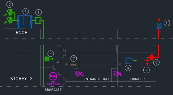
c) Let’s assume that the entire air is being supplied to the entrance hall (Figure 5 and 6). The air flowing at a rate of 14 400 m³/h passes through the doorway between the entrance hall and the zone engulfed in fire. Subsequently, the air is being transported out of the building by the provided smoke ventilation system. A hole in the wall between the zone engulfed in fire and the entrance hall with an effective area of 1 m² is planned for smoke exhaust compensation when the door is closed. In order to maintain the 2 m/s velocity of air flowing through the door, we need to supply additional 7 200 m³/h of air to the entrance hall. In total, we supply 14 400 m³/h + 7 200 m³/h = 21 600 m³/h of air to the entrance hall. Let’s analyse the resistance and system output generated with this airflow criterion.
|
Figure 5. Air flowing through the doorway from one area to another. |
1. Pressure differential systems unit, the iSWAY air supply unit 2. Damper-controlled double supply louvre system 3. SEFL/REF smoke exhaust fan 4. STW/GA air supply grille with a damper 5. Automatic opening window with an actuator – smoke exhaust compensation feature 6. TAP rectangular acoustic silencer 7. P-MACF remote pressure sensor 8. KWP-P-E fire ventilation damper with an actuator 9. SDS-STW smoke exhaust grille |
The air flowing through the doorway from one zone to the other at a rate of 2 m/s generates a resistance of 6 Pa (Table 1). As we have a single doorway, the total resistance equals 6 Pa. We use mechanical exhaust ventilation, so no additional resistance is present in this case. The total resistance thus amounts to 6 Pa. We can state that all openings in the staircase require a resistance of at least 6 Pa so that the air passes through an open door in the direction of the exhaust grille of the smoke ventilation system.
The biggest opening in the staircase is an open emergency exit door outside the building. Let’s assume that its area is 2 m². In order to ensure a flow resistance of 6 Pa, the airflow rate must equal 2.0 m/s. It seems that – considering that the air should flow to the staircase at a rate of 2 m/s – we must supply 14 400 m³/h (we shall not include any other leaks in the staircase in this analysis). Therefore, the total amount of air required to meet the airflow rate criterion with such a mechanical exhaust is 14 400 m³/h + 14 400 m³/h = 28 800 m³/h. Now, we should consider a proper placement of air supply points in the staircase in order not to exceed door opening force at any storey, i.e. 100 N. This also applies to the door in the entrance hall to the zone engulfed in fire. Air is supplied to the entrance hall and staircase by two independent devices.
ATTENTION! In case of the pressure difference criterion leaks in the entrance hall and staircase may be significantly lower (Figure 1). The fan must therefore supply extremely different quantities of air depending on the number of open and closed doors. Only devices with valid certificates stating fan working ranges and system response times should be used. Additionally, the smoke ventilation system for the zone engulfed in fire shall be designed for the output rate of 14 400 m³/h.
|
Figure 6. Air flowing through the doorway from one area to another. |
1. Pressure differential systems unit, the iSWAY air supply unit 2. Damper-controlled double supply louvre system 3. SEFL/REF smoke exhaust fan 4. STW/GA air supply grille with a damper 5. WKP-O-E-T transfer damper with an actuator 6. TAP rectangular acoustic silencer 7. P-MACF remote pressure sensor 8. KWP-P-E fire ventilation damper with an actuator 9. SDS-STW smoke exhaust grille |
The air flowing through the doorway from one zone to the other at a rate of 2 m/s generates a resistance of 6 Pa (Table 1). As we have a single doorway, the total resistance equals 6 Pa. We use mechanical exhaust ventilation, so no additional resistance is present in this case. The total resistance thus amounts to 6 Pa. We can state that all openings in the staircase require a resistance of at least 6 Pa so that the air passes through an open door in the direction of the exhaust grille of the smoke ventilation system.
The biggest opening in the staircase is an open emergency exit door outside the building. Let’s assume that its area is 2 m². In order to ensure a flow resistance of 6 Pa, the airflow rate must equal 2.0 m/s. It seems that – considering that the air should flow to the staircase at a rate of 2 m/s – we must supply 14 400 m³/h (we shall not include any other leaks in the staircase in this analysis). Therefore, the total amount of air required to meet the airflow criterion with such a mechanical exhaust ventilation is: 14 400 m³/h + 21 600 m³/h = 36 000 m³/h. Now, we should consider a proper placement of air supply points in the staircase in order not to exceed door opening force at any storey, i.e. 100 N. This also applies to the door in the entrance hall to the zone engulfed in fire. Air is supplied to the entrance hall and staircase by two independent devices.
ATTENTION! In case of the pressure difference criterion leaks in the staircase may be significantly lower (Figure 1). The fan must therefore supply extremely different quantities of air depending on the number of open and closed doors. Since the smoke exhaust compensation is carried out by the air supplied to the entrance hall, in case of the pressure difference criterion (Figure 1) the output rate is 21 600 m³/h. The air supply device supplies the constant amount of air at all times – when the door is both closed and open. Only devices with valid certificates stating fan working ranges and system response times should be used. Additionally, the smoke ventilation system for the zone engulfed in fire shall be designed for the output rate of 21 600 m³/h.
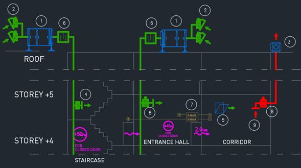
In the second case, the entire air is also supplied to the entrance hall. The air flowing at a rate of 14 400 m³/h passes through the doorway between the entrance hall and the zone engulfed in fire. Subsequently, the air is being transported out of the building by the provided smoke ventilation system. Smoke exhaust compensation with the door closed is ensured by an independent device that supplies air to the zone engulfed in fire.
d) Let’s assume that the entire air is being supplied to the entrance hall (Figure 7). The air flowing at a rate of 14 400 m³/h passes through the doorway between the entrance hall and the zone engulfed in fire. Subsequently, the air is being transported out of the building by the provided smoke ventilation system. Smoke exhaust compensation with the door closed is ensured by an air supply system controlled by a pressure difference sensor equipped with a set of dampers and quick-acting actuators. When the door is open, the air is being supplied to the entrance hall in order to ensure that the rate criterion of 2 m/s is met. However, when the door is closed, the air is being supplied directly to the zone engulfed in fire. Let’s analyse the resistance and system output generated with this airflow criterion.
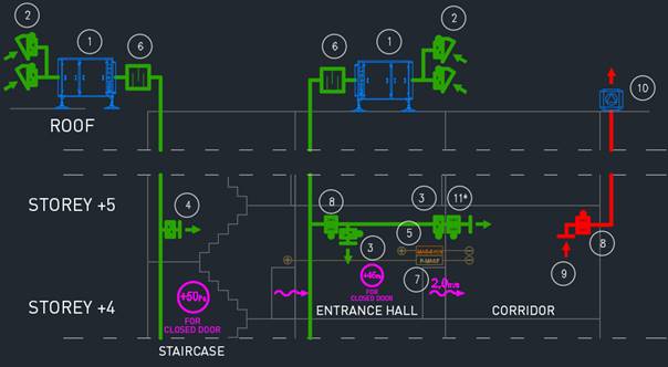
Figure 7. Air flowing through the doorway from one area to another.
The air flowing through the doorway from one zone to the other at a rate of 2 m/s generates a resistance of 6 Pa (Table 1). As we have a single doorway, the total resistance equals 6 Pa. We use mechanical exhaust ventilation. Therefore, no additional resistance is present in this case. The total resistance thus amounts to 6 Pa. We can state that all openings in the staircase require a resistance of at least 6 Pa so that the air passes through an open door in the direction of the exhaust grille of the smoke ventilation system.
The biggest opening in the staircase is an open emergency exit door outside the building. Let’s assume that its area is 2 m². In order to ensure a flow resistance of 6 Pa, the airflow rate must equal 2.0 m/s. It seems that – considering that the air should flow to the staircase at a rate of 2 m/s – we must supply 14 400 m³/h (we shall not include any other leaks in the staircase in this analysis). Therefore, the total amount of air required to meet the airflow rate criterion with such a mechanical exhaust is 14 400 m³/h + 14 400 m³/h = 28 800 m³/h. Now, we should consider a proper placement of air supply points in the staircase in order not to exceed door opening force at any storey, i.e. 100 N. This also applies to the door in the entrance hall to the zone engulfed in fire. Air is supplied to the entrance hall and staircase by two independent devices.
ATTENTION! In case of the pressure difference criterion leaks in the staircase may be significantly lower (Figure 1). The fan must therefore supply extremely different quantities of air depending on the number of open and closed doors. Smoke exhaust compensation and entrance hall air supply are carried out by a single device. Its output rate is thus always 14 400 m³/h, regardless of whether the door is open or closed. Only devices with valid certificates stating fan working ranges and system response times should be used. Additionally, the smoke ventilation system for the zone engulfed in fire shall be designed for the output rate of 14 400 m³/h.
e). Let’s assume that the entire air is being supplied to the entrance hall (Figure 8). The air flowing at a rate of 14 400 m³/h passes through the doorway between the entrance hall and the zone engulfed in fire. Subsequently, the air is being transported out of the building by the provided smoke ventilation system. Smoke exhaust compensation with the door closed is ensured by an independent device that supplies air to the zone engulfed in fire. Air supply systems (both for the entrance hall and the zone engulfed in fire) have the same output rate, but they alternate and are regulated by a pressure difference sensor. When the door is open, the device supplies air to the entrance hall, ensuring that the rate criterion of 2 m/s is met, while when the door is closed, the amount of air is drastically lowered in order to meet the pressure difference criterion (Figure 1). At the same time, the device that supplies air for the purposes of smoke exhaust compensation provides the absolute minimum amount of air (door open) in order to drastically increase it to 14 400 m³/h (door closed). Let’s analyse the resistance and system output generated with this airflow criterion.
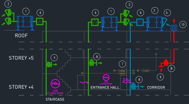
Figure 8. Air flowing through the doorway from one area to another.
The air flowing through the doorway from one zone to the other at a rate of 2 m/s generates a resistance of 6 Pa (Table 1). As we have a single doorway, the total resistance equals 6 Pa. We use mechanical exhaust ventilation. Therefore, no additional resistance is present in this case. The total resistance thus amounts to 6 Pa. We can state that all openings in the staircase require a resistance of at least 6 Pa so that the air passes through an open door in the direction of the exhaust grille of the smoke ventilation system.
The biggest opening in the staircase is an open emergency exit door outside the building. Let’s assume that its area is 2 m². In order to ensure a flow resistance of 6 Pa, the airflow rate must equal 2.0 m/s. It seems that – considering that the air should flow to the staircase at a rate of 2 m/s – we must supply 14 400 m³/h (we shall not include any other leaks in the staircase in this analysis). Therefore, the total amount of air required to meet the airflow rate criterion with such a mechanical supply and exhaust is 14 400 m³/h + 14 400 m³/h + 14 400 m³/h = 43 200 m³/h. Now, we should consider a proper placement of air supply points in the staircase in order not to exceed door opening force at any storey, i.e. 100 N. This also applies to the door in the entrance hall to the zone engulfed in fire. Air is supplied to the entrance hall and staircase by two independent devices.
ATTENTION! In case of the pressure difference criterion leaks in the staircase may be significantly lower (Figure 1). The fan must therefore supply extremely different quantities of air depending on the number of open and closed doors. Only devices with valid certificates stating fan working ranges and system response times should be used. Additionally, the smoke ventilation system for the zone engulfed in fire shall be designed for the output rate of 14 400 m³/h.
In order to ensure the rate criterion of 2 m/s by means of gravitational exhaust ventilation, the following should be taken into consideration: the bigger the resistance of air flowing from the stairwell/entrance hall in the direction of the exhaust located outside the building, the bigger the output rate of devices that supply air.
In order to ensure the rate criterion of 2 m/s by means of mechanical exhaust ventilation, the following rule should be followed: the underpressure in the zone engulfed in fire should be as low as possible due to the fact that the force vectors applied to the closed door between the underpressure and overpressure zones add up. As the door surface, closer setpoint and door handle location may differ, we suggest making calculations that would confirm the door opening force of not more than 100 N.
Follow us on social media accounts to stay up to date with REHVA actualities
0