


Stay Informed
Follow us on social media accounts to stay up to date with REHVA actualities
|
|
|
|
Ben Bronsema | Regina Bokel | Harry Bruggema | Ronald van Luijk |
PhD, BEng.,Bronsema Consult/TU Delft, Faculty of Architecture Dept. AE + T | PhD.,TU Delft, Faculty of Architecture Dept. Architectural Engineering +
Technology | BEng.,Peutz Consulting Engineers | MSc.,Green Building Engineering |
|
|
|
|
Arjan van Mook | Martijn de Potter | Otto Meerstadt | Maarten Quist |
BEng.,Van Delft Group Mechanical Contractors | MSc.,NWA Architects | MSc.,Dutch Green Company | MSc.,(Ex) Dutch Green Company |
The solar chimney is a dominant architectural element and a typical example of climate-responsive architecture. By using the sun as a driving force for the extraction of ventilation air, the solar chimney can make an essential contribution to natural air conditioning in buildings. However, of even more importance is the solar chimney’s absorption of solar energy, both thermal and electric, that can be used to heat buildings, restore the thermal equilibrium in the soil (through TES systems) and power pumps and auxiliary fans. This can make an important contribution to achieving energy neutral buildings.
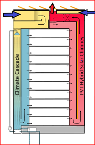
Figure 1. Natural Air Conditioning using PVT solar chimney 3.0.
The design and performance of the innovative solar chimney for use in generic applications have been described at length (Bronsema, B., 2013/A, B, C). A team of designers faced the interesting challenge of developing the concept for a specific project, Hotel BREEZE Amsterdam, into a PVT hybrid solar chimney 3.0.
With the help of valued input from various design partners, a robust solar chimney was designed that carefully balances architectural, thermal, aerodynamic and energy performance.
An application was submitted for a BREEAM innovation credit for the PVT solar chimney 3.0 which describes the calculated performance requirements in detail. The experiences gained during the design, detailing and implementation phases will be meticulously recorded, and the thermal, aerodynamic and energy performance of the solar chimney will be monitored for the period of one year after completion of the project. The design documents will be continuously updated based on these experiences and progressive insights. The final design documents will then be made available for wide application of the solar chimney in the air-conditioning sector. In the meantime, the authors hope that the solar chimney will be implemented in various new-build or renovation projects in the short term, because ‘Natural Air-conditioning: What are we waiting for?’ (Bronsema, B., et al., 2018).
In the Earth, Wind & Fire concept, the solar chimney is multifunctional:
1 extraction of ventilation air (aerodynamic performance)
2 solar energy harvesting (energy performance)
3 architectural value (architectural performance)
These performance requirements need to be prioritised in the design, whereby architecture (3) will often be dependent on (1) and (2).
The total ventilation rate for hotel rooms and general-purpose rooms is 25,000 m³.h⁻¹. To reduce internal pressure loss, the air speed in the solar chimney will be ≈ 1.5 m.s⁻¹. To facilitate cleaning, the minimum depth has been set at 0.65 m, which means the width will be ≈ 7.0 m. The architect translated these design principles into a twin solar chimney of 2 x 3.5 m wide (see Figures 2 and 3). The energy performance of this solar chimney proved more than sufficient to heat the domestic hot water supply and restore the thermal equilibrium in the soil through the TES system.
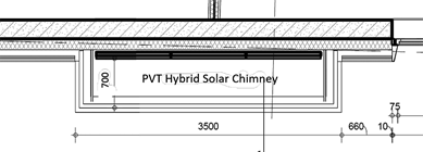
Figure 2. Detail of the PVT solar chimney in Hotel BREEZE Amsterdam (OZ Architects).
Generally speaking, it makes the most sense to optimise the design of a solar chimney to achieve the best energy performance. Because there is little pressure loss in the exhaust system, there is little to be gained by saving on fan energy. However, solar energy could contribute substantially to heating the building. In principle, the energy performance of the system can be increased or decreased, whereby the width of the solar chimney for a given height and chimney type will be the key design variable. A consequence is that the integration of the solar chimney in a wall may conflict with the architecture of the building.
Figure 3 displays the sunny side of the hotel with the twin solar chimney in the south-west wall. The black areas are the building-integrated PV panels. Each solar chimney is 3500 mm wide and 650 mm deep. The front and side faces are glazed. The total height is ≈ 33 m and the total gross surface area on the south-west faced side is ≈ 230 m². The combined gross surface area of the south-east and north-west faced side is ≈ 42.5 m². The net glazed surface area was calculated with a reduction factor (R) of 0.95 of the gross surface areas to take the account of structural elements that obscure incident solar radiation.

Figure 3. Twin Solar Chimney – NWA Architects /OZ Architects.
The most important selection criteria for the glass curtain wall were:
· the highest possible g-value for maximum transmission of the incident solar radiation to the absorber
· the lowest possible U-value to reduce heat loss to the outside air
· maximum transparency of the glass wall through application of structural glazing without window post
· of linear thermal bridges
In the test setup of the Earth, Wind & Fire research project (Bronsema, B. 2013) the glass type SGG Planitherm Solar 4/15/4 argon was used. This glass is no longer obtainable as of 2017 and therefore the best available equivalent glass type SGG Eclaz 10-15-6 (diamant-argon/air-eclaz planiclear) will be used with physical properties of
· g = 0.71 [−]
· U = 1.1 [W.m⁻².K⁻¹]
The glass wall is constructed using structural glazing without window posts.
Dynamic simulations have demonstrated that a solar chimney fitted with a thermally light, low-accumulating backwall will display better energy performance than a chimney with a thermally heavy backwall (Bronsema, B., 2013/A). The backwall of the solar chimney in Hotel BREEZE Amsterdam is constructed of light PV panels mounted on an insulation layer that are not affected by heat accumulation.
The test setup of the Earth, Wind & Fire research project used Mirotherm absorber, which is a 0.5 mm thick anodised aluminium plate with a spectrally selective coating and an emission coefficient of ≈ 0.05. To increase exergetic performance, the absorbers in the twin solar chimney in Hotel BREEZE were attached to PV panels. The emission coefficient of these panels was considerably higher (≈ 0.87) than that of the spectrally selective absorber. The consequence was that the temperature of the glass wall was higher and there was more heat loss to the outside air. However, calculations reveal that this effect is minor, primarily due to the low U-value of the glass curtain wall.
The absorber is constructed of 98 PV panels of the type Astronergy 300Wp mono Full Black, with additional power optimisers (brand: SMA/TIGO). This panel was selected for its black colour and the availability of an attestation of equivalence, which was required for the Energy Performance calculation. The module efficiency of these panels is 18.34%.
Insulation with an Rc ≥ 5,0 [m².K⁻¹.W⁻¹] will be used
The application of an anti-corrosive and dirt-repellent coating can significantly enhance the performance of a solar chimney and reduce the amount of cleaning needed. One such coating is the Vindico PV+ especially developed for PV panels (http://www.vindico.info). This coating is anti-reflective, which also helps to improve energy performance. The manufacturer claims that using Vindico PV+ increases light transmission by up to 5%. The positive influence of this coating on the g-value (in accordance with EN 410) is not known.
The solar chimney must be accessible for inspections and maintenance (including cleaning) of both the glass wall and the PV panels. This has been taken into account in the design.
The air exhaust volume rate in the solar chimney must not be significantly influenced by wind pressure and the inherent infiltration of outside air. The design using structural glazing is expected to make this infiltration negligible.
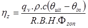
The thermal efficiency of a solar chimney is defined as the ratio between the net amount of heat extracted by the airflow divided by the incident solar radiation. The formula is as follows (Bronsema, B. 2013/A):
| (1) |
Where
ηz | = | thermal efficiency of the solar chimney under reference conditions | |
qv | = | volumetric flow rate of the passing air | [m³.s⁻¹] |
ρ | = | air density | [g.m⁻³] |
c | = | specific heat of the air | [J.g⁻¹.K⁻¹] |
θout | = | temperature of the outgoing air | [°C] |
θin | = | temperature of the incoming air | [°C] |
B | = | chimney width | [m] |
H | = | chimney height | [m] |
Φsun | = | solar radiant flux | [W.m⁻²] |
R | = | net reduction factor in relation to gross glass area | [-] |
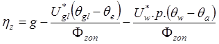
This formula can be reduced to:
| (2) |
Where
g | = | g-value of the glass | [-] |
U*gl | = | heat transfer coefficient of the glass surface → outside air | [W.m⁻².K⁻¹] |
U*w | = | heat transfer coefficient of the wall surface → inside air | [W.m⁻².K⁻¹] |
θgl | = | glass temperature | [°C] |
θe | = | outside temperature | [°C] |
θw | = | wall temperature | [°C] |
θa | = | temperature behind the inner backwall | [°C] |
p | = | total interior surface area/front surface area | [-] |
This
formula is very intuitive. The thermal efficiency of a solar chimney is
determined by the three factors in the formula:
1. The g-value of the glass (easily the most important factor). The g-value of the chosen glass type is ≈ 0.71. This is also the maximum efficiency (assuming zero heat loss). The use of Vindico+ could lead to an increase of ≈ 5%, although this is somewhat speculative.
2. The heat loss to the outside
air, determined by the U-value of the glass and the difference between the
glass temperature and the outside temperature, which is the next highest heat
loss factor.
3. The heat loss through the
inner backwall, determined by the U-value of the backwall, the depth of the
solar chimney and the difference between the wall temperature and temperature
of the air behind it. This is the lowest heat loss factor thanks to the use of high-quality
insulation with a low U-value.
The wall and glass temperatures in a solar chimney are interrelated functions of the radiation and convection heat transfer coefficients, which are in turn functions of the geometric ratios, air speed and the solar radiant flux.
Dynamic simulations demonstrate that an annual efficiency of 55–60% is achievable. An annual thermal efficiency of 60% was assumed based on the application of a good quality glass coating.
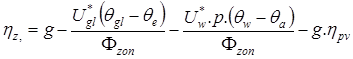
The absorber consists of PV panels, which means that part of the incident solar radiation is converted into electrical energy, to the detriment of the thermal efficiency. Formula 2 then becomes:
| (3) |
Where
ηpv | = | PV panel efficiency |
The
reduction of the thermal efficiency leads to a reduction in heat output and thermal
draught. However, the reduction of the low-grade heat output is compensated by
the high-grade energy output of the PV panels, which will increase the
exergetic efficiency of the solar chimney. The reduction of thermal draught can
be compensated by an auxiliary fan.
Points
of concern regarding the thermal properties of this concept are:
· The radiation and heat transfer ratios in the solar chimney are changed as a result of other properties of the absorber, resulting in 1.5–2% more heat loss.
· Because part of the solar radiation is reflected onto the glass wall, the effective efficiency of the PV panels is reduced by a factor g. For the selected Astronergy panels with a module efficiency of 18.34%, this means a reduction of up to (0.71*18.34) = 13%
The temperature in a solar chimney under the influence of incident solar radiation is higher than the outside temperature, which decreases the efficiency of the PV panels. For a temperature of 30°C and a temperature coefficient of −0.416%.K⁻¹, this amounts to a reduction of ≈ 2.0% in relation to the reference temperature of 25°C.
A
thermal efficiency of 50% was assumed for the subsequent calculations.
The Earth, Wind & Fire research project used the ESP-r dynamic simulation model (Gontikaki, et al., 2010) to study the dynamic behaviour and estimate the annual energy performance of the solar chimney. This model was developed at TU Eindhoven and can be used by designers to analyse complex relationships between the inside and outside climate of a building based on architecture, building mass, air currents and climate systems (including the control system). It is a flexible and powerful tool and ideal for simulating innovative technologies.
In the conceptual phase, it is the architect who lays the foundation for the successful architectural integration of a solar chimney in a building. A user-friendly calculation model was designed for the purposes of this intuitive and interactive phase of the design that can be used to visualise different architectural variants and their energetic consequences with a click of the mouse (Bokel, R., 2011).
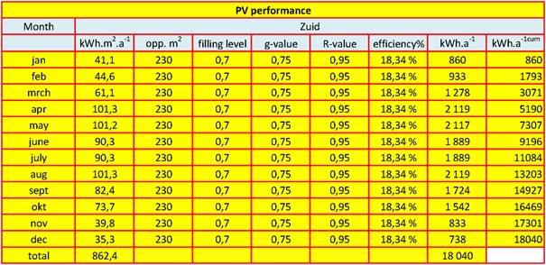
The estimated annual yield of the PV panels in the twin solar chimney is about 18,000 kWh (see Table 1). This assumes the specific monthly solar radiation level applied in NEN 5060:2008. The coverage of the PV panels is relatively low. In principle, better coverage could be achieved by optimising the width of the solar chimney to match the size of the PV panels (1654 x 989 mm).
Table
1. Energy yield of PV panels.
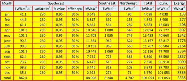
The estimated annual thermal energy yield of the twin solar chimney is about 101,000 kWh (see Table 2). This assumes the specific monthly solar radiation level used in NEN 5060:2008 and an efficiency of 50%. Table 2 reveals that the contribution of the side walls is limited (≈ 12.9%).
The heat harvested in the solar chimney has a low temperature level and hence a low exergetic value, which means direct use for HVAC and domestic hot water supply is limited. The following options are available for the optimum use of the low-grade heat:
· The energy yield during the heating season (from mid-October to mid-April) is ≈ 31.6% of the total yield. In principle, this heat can be used to heat the building and the domestic hot water supply directly or indirectly using heat pumps.
· The energy yield during the cooling season (mid-April to mid-October) is ≈ 68.4% of the total annual yield. In principle, this heat can be used to heat the domestic hot water supply directly or indirectly using heat pumps.
· Another important consumer of heat in the cooling season is the TES system, which needs to compensate for the heat used during the heating season and restore the thermal equilibrium in the ground.
Table 2. Thermal energy yield.
The temperature level of heat determines the quality of the energy and is expressed in the exergy value Exq. The exergy value of PV electricity is equal to the energy value: Expv = W
The exergy value of heat is calculated with the formula:
|
Where
T0 | = | ambient air temperature | [K] |
T | = | temperature of the heat flow | [K] |
Qth | = | quantity of heat | [W] |
Under reference conditions (solar radiation of 400 W.m⁻² and an outside temperature of 20°C; see below), the temperature of the extracted air above the solar chimney is ≈ 30°C. The exergy value of the hot air is only 3.3% at this temperature.
Figure 4 displays the cumulative annual energy yield of the solar chimney, subdivided into thermal energy, PV electricity and the exergetic value of the thermal energy.
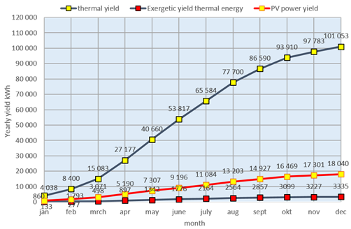
Figure 4. Cumulative annual yield of the PVT solar chimney.
The thermal draught is a function of the outside temperature and the average temperature in the solar chimney, which in turn is a function of the solar radiant flux, the chimney efficiency and the air flow rate. The principle of the EWF concept was that the thermal draught would be sufficient to compensate for the pressure loss of the air exhaust system, including the solar chimney itself (under reference conditions). The reference conditions are defined as follows (Bronsema, B., 2013):
· Outside temperature θe =20 [°C]
· Radiant flux ɸsun=400 [W.m⁻²]
The reference radiant flux is the average daily radiation on sunny days during the summer months (even if less sunny days are included, the average daily radiant flux is still ≈ 350 W.m⁻²).
Figure 5 reveals that the required thermal draught is only ≈ 6.6 Pa under the reference conditions (R). It would be virtually impossible and certainly not cost effective to design the exhaust system based on such low-pressure losses. The auxiliary fan could be used to create sufficient draught in these conditions.
Figure 5 also clearly reveals the influence of the outside temperature on the thermal draught, that can increase to > 40 Pa on cloudy days and > 50 Pa on sunny winter days if the outside temperature is low. The solar chimney functions as a thermal chimney in this situation and a flow control system is necessary to compensate for the variating thermal draught.
When the kitchen is in operation, the kitchen exhaust air, which has a flow rate of ≈ 7500 m³.h⁻¹, is diverted away from the solar chimney. In this case, the air speed falls to ≈ 1.1 m.s⁻¹ and the air temperature can increase to ≈ 45°C. The calculated temperatures are well below the threshold of 80°C, when tempered glass must be applied.
To compensate for overheating caused by potential stagnation in the extraction system, a maximum temperature sensor will be installed at the top of the chimney which will restore the air flow.
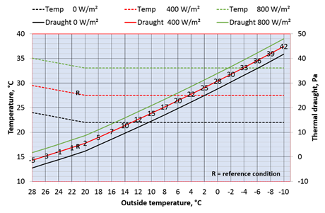
Figure 5. Outgoing air temperature and thermal draught as a function of the outside temperature and radiant flux (air flow rate of 25,000 m³.h⁻¹).
The principle of heat recovery is displayed in Figure 6. The heat extracted from the solar chimney serves as a heat source for a heat pump, which upgrades the heat and transfers it to the hotel’s hot water supply for heating the building, domestic hot water and to restore the thermal equilibrium in the ground through the TES system. The cooled air is then extracted through the Ventec heat exchanger on the leeward side of the building (Bronsema, B., et al., 2018/C).
It will be an interesting challenge to optimise the system in combination with the domestic hot water storage capacity. To be energetically efficient, the heat pump will preferably operate under the highest possible source temperatures, in this case the hours of optimum sunshine and radiation intensity.
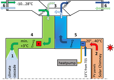
Figure 6. Principle design of air supply and extraction using the Ventec heat exchanger.
The rpm-controlled extraction fan will maintain the exhaust air flow rate at 25,000 m³.h⁻¹, independent of the thermal draught of the solar chimney and the wind forces on the side wall.
The positive thermal draught of the solar chimney depends on the solar radiant flux and the outside temperature and can vary between −5 Pa and +50 Pa (see Figure 4).
The extent of the negative draught depends on the outside temperature θe and the simultaneous solar radiant flux Φsun. Assuming very extreme conditions, with an outside temperature of 35°C, a thunderstorm that practically blocks out all sunlight, and heating of ventilation air in the solar chimney reduced to zero (and if heat transmission through the glazing and water accumulation in the solar chimney are both negligible), the negative draught could increase to ≈ −10 Pa.
Bokel, Regina 2011. Een gebruiksvriendelijk rekenmodel voor het initieel ontwerp van een zonneschoorsteen. Technische Universiteit Delft - Faculteit Bouwkunde – Afdeling AE+ T.
Bronsema, B. 2013/A. Earth, Wind & Fire – Natuurlijke Airconditioning. PhD Thesis TU Delft. Uitgeverij Eburon Delft. ISBN 978 90 5972 762 5. TU Delft Repository https://tudelft.on.worldcat.org/oclc/845637529.
Bronsema, B. 2013/B Earth, Wind & Fire – Natural Airconditioning [1] Research objectives and Methods. Conference paper 11th REHVA world congress CLIMA 2013.
Bronsema, B. 2013/C Earth, Wind & Fire – Natural Airconditioning [2] Results
of the research. Conference paper 11th REHVA
world congress CLIMA 2013.
Bronsema, B. et al2015. Earth, Wind &
Fire – Natural Air-conditioning. Conference paper Healthy Buildings
Europe 2015.
Bronsema, B. et al 2018. Natural Air-conditioning:
What are we waiting for?REHVA Journal April 2018.
Gontikaki, M. enHouben, J. 2010. Calibration & Validation Report of the ESP-r solar chimney model. TU Eindhoven, faculty of Architecture Dept. Building Physics & Systems.
Follow us on social media accounts to stay up to date with REHVA actualities
0