


Stay Informed
Follow us on social media accounts to stay up to date with REHVA actualities
|
|
|
|
Jens TeichmannRWTH Aachen University, | Alexander KümpelRWTH Aachen University, E.ON Energy Research Center, Institute for Energy
Efficient Buildings and Indoor Climate’, Aachen, Germany | Paul MathisRWTH Aachen University, E.ON Energy Research Center, Institute for Energy
Efficient Buildings and Indoor Climate’, Aachen, Germany | Dirk MüllerRWTH Aachen University, E.ON Energy Research Center, Institute for Energy
Efficient Buildings and Indoor Climate’, Aachen, Germany |
In order to have the air conditioned in terms of heating, cooling, dehumidification, humidification for the use in buildings, AHUs use thermal energy as well as electric energy. In most cases, hydronic networks supply the air with this thermal energy using water to air heat exchangers (e.g. cooler, preheater). These hydronic networks consist of pumps, pipes and valves, which are dimensioned for the full load case. Operation points, close to the full load case are rare in real operation. For this reason, the systems usually operate in inefficient part load mode [1].
Depending on the requirements, we can arrange single heat exchangers, valves and pipes in a different hydronic configuration, which are called hydronic standard circuits (Figure 1) [2]. For instance, the mixing circuit and the injection circuit are well qualified for a uniform air temperature distribution downstream of the heat exchanger. The injection and the diverting circuit guarantee low dead times in case of suddenly appearing thermal loads (e.g. for frost protection). These circuits either vary the water volume flow at a constant supply temperature (systems 1 and 4 in Figure 1) or the water inlet temperature in the heat exchanger with a constant volume flow (systems 2 and 3 in Figure 1). Today, the valve lifts are the only actuating variables in the circuits, controlling the control variable (temperature, humidity, enthalpy) of the air downstream the heat exchanger. In this case, the pump runs at its maximum speed (older pumps) or varies its pressure depending on the volume flow internally (newer pumps) resulting in unnecessarily high pump energy consumption. Typical valves for building technology have low adjustment speeds (1-2 minutes for full valve lift), which we need to consider in operation and control parameter settings of the circuits [2].
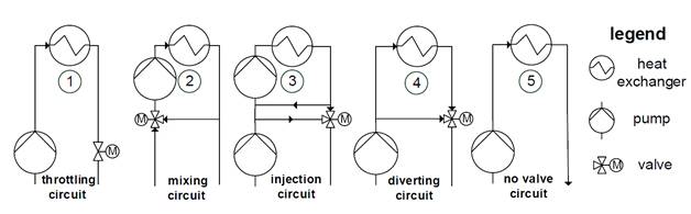
Figure 1. Hydronic standard control systems.
For good control quality in part load cases, valves are dimensioned via valve authority criteria of values between 0.3 and 0.5 [2]. The valve authority is defined as the pressure loss over the fully open valve divided by the pressure loss of the closed valve at design point conditions. This leads to pressure losses over fully open valves being as high as the entire pressure loss of the rest of the hydronic circuit, including the heat exchanger. However, today even systems with high valve authorities can have poor control quality. One reason for this is the use of demand-oriented ventilation in AHU, which causes high ratios of design and minimum thermal power of more than 35 [2], as well as high nonlinearities in the controlled systems. Therefore, those systems are very hard to control with constant PID parameters for all load situations. In real AHU systems, this can lead to permanent oscillations. To avoid permanent oscillations, slow PID parameters can be used, so it can take hours to reach the temperature set value.
In addition, the effects of those standard hydronic concepts can even decrease efficiencies of heat sources (e.g. condensing boiler) or destroy the stratification of thermal storages by high return temperatures, as happened on one occasion in our institutes’ main building, for instance. In our own facilities, which we also use for experimental purposes, most heating coils of AHUs including some reheaters are equipped with injection circuits. However, reheaters do not need injection circuits, as frost protection is not required. Adding the design volume flows of all injection circuits, we have a water volume flow of more than 23 m³/h in our facilities, even when there is nearly no heat demand. To minimize the water volume flow rates, we installed balancing valves in most of the lower bypasses of the injection circuits.Nonetheless, for changes like these we have to consider negative effects on valve authority, which can decrease controllability of the systems again.
One reason
for the inefficient state of the art of the operation of hydronic systems is
the integration of constant speed pumps in the past, later substituted by pumps
with a small ratio of maximum to minimum pump speed (frequency ratio) of two,
for instance. However, due to latest developments in pump industry, pumps with
frequency ratios up to 10 and a change of the pump speed within milliseconds
are available, which enable them to become an important part in new AHU control
concepts.
In order to achieve pump energy savings and improve control quality, we analysed the current control concepts for possible improvements taking into account the regulating variables “pump speed” and “valve lift”. In this paper, we will focus on three concepts, which mainly address potential electric energy savings of pumps:
1. Throttling circuit: First pump then valve control (1 in Figure 1)
2. No valve: Pump only control (5 in Figure 1)
3. Mixing circuit: Constant mixing ratio for lower loads with pump control (2 in Figure 1)
All concepts work on two different modes depending on the actual relative thermal load.
The first concept uses the pump to control the temperature for higher loads with fully open valve until the minimum pump speed is reached in smaller loads [2]. Then the valve takes the control task, whereby the pump operates at minimum speed.
The second concept uses no valve and only the pump for control purposes, which results in a maximum reduction of pump energy. As we do not need a valve, we have a decrease of up to 50% of hydronic resistance in the circuit. Due to the reduced resistance, a smaller pump with less minimum power can be used. If the minimum pump speed is too high in low part load condition, the pump changes to pulsing operation, i.e. it switches on and off in certain intervals. This concept is only appropriate for well-designed hydronic systems, where no other pumps push in this local circuit and the volume flow becomes zero if the pump is turned off.
The third concept is suitable for heat exchangers, which have a high ratio of design to minimal thermal power. Here, in part load cases the 3-way-valve stays at a constant medium mixing position (e.g. 65% open) and the pump takes the control part. For higher loads, as soon as the pump speed exceeds 80%, the valve begins to open slowly until it reaches the 100% open position.
For the evaluation of the new concepts, we built a testing facility (see [1]) and performed dynamic simulations with Modelica (models will be available open source on https://github.com/RWTH-EBC/AixLib ). To proof the transferability of the concepts, we are currently performing a field test on two further AHUs.
Although we used the testing facility to demonstrate pump energy savings of up to 86% for the preheater in [1], its main task is to demonstrate the control quality of standard and newly developed concepts. In the testing facility we focus mainly on the components cooler and preheater (for technical data see Table 1), which can be used for adiabatic humidification. Therefore, the preheater has to reach high temperature differences of more than 45 K during full load.
Table 1. Technical design data of AHU heat exchanger systems.
Component | Humidity air g/kg | Temp. air in°C | Thermal power in kW | Pump speed min/max in 1/min | Pump power min/max in W | Hydr. temp. in°C |
Preheater | 0/0 | −15/42 | 57.7 | 800/3700 | 5/120 | 70/50 |
Cooler | 23.8/13.3 | 45/20 | 53.4 | 750/2900 | 75/1100 | 6/12 |
Reheater | 0/0 | −13/9 | 22.3 | 500/4800 | 2/60 | 70/50 |
In order to evaluate the control quality in different load situations, we performed defined test cycles (see Figure 2 and 3), in which we varied the air volume flow from 3,000 m³/h (left, design value) to 2,000 m³/h (middle) and finally to 1,000 m³/h (right). Depending on the component, we varied the set temperature (preheater) or the entrance temperature (cooler) between 15°C and 35°C in 5 K steps hourly, whereby the control parameters stayed constant. We used ambient air for the entrance conditions, so results should be compared with care, as the entry conditions are not perfectly the same. We determined the PID control parameters for the standard concept applying controller tuning methods like Ziegler and Nichols, which resulted in poor control qualities. For this reason, we used control parameters from experience from diverse test measurements with a good control quality. Determining good control parameters for the new concepts took much less effort compared to the standard control concepts.
For the first concept, which we tested for the preheater, the control quality does not change significantly compared to the standard case [1]. We demonstrated the second concept with the cooler, cooling down the entering air (orange) to a set temperature of 13°C (red: set value, blue: exit value) with the pump (Figure 2). As there was nearly no dehumidification, which causes more than 44% of the coolers design power, the pump operates mostly in on-off (pulsing) mode or is close to the minimum pump power (green) of about 75 W, which is less than 10% of the design power (1,100 W). Only at the highest entrance temperatures at 3,000 m³/h and 2,000 m³/h the pump operates at a speed of up to 1050 1/min. In these cases, we obtain a good control quality, with small deviations on the scale of measurement accuracy. The pulsing pump operation worked acceptable at 3,000 m³/h (deviation < 0.5 K) and caused high deviation of more than 1.5 K at 1,000 m³/h. Those deviations are not acceptable and cause an increase of cooling energy, which overcompensates pump energy savings. The reason for this effect is that the time constants of the controlled system vary with the air volume flow, whereby the interval of pulsing pump operation stays constant.
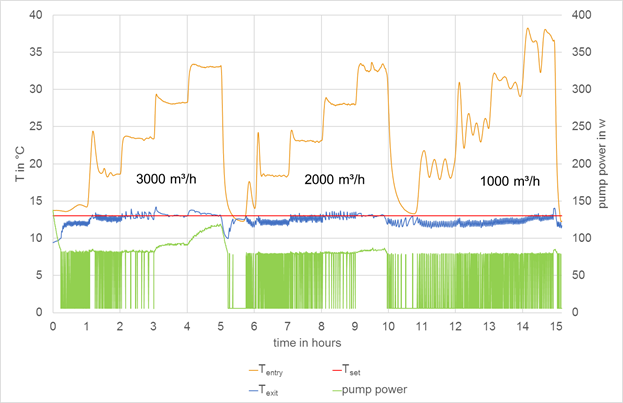
Figure 2. Pump only control for the cooler.
The exit temperatures of the preheater for the third concept (light blue) in comparison to the standard mixing circuit control (blue) illustrates in Figure 3. At 3,000 m³/h, the third concept achieves the new set value (red) faster and more precisely compared to the standard concept. At lower air volume flow rates there are small overshoots and oscillations of less than 0.5 K for 2,000 m³/h or around 1 K for 25°C at 1,000 m³/h. The highest oscillations are caused by pulsing operation of the pump, as observed in the electric power trend of the pump (green). The maximum power for this test is 9 W and the lowest power 2.5 W (pump off). This corresponds with a reduction of 96% pump energy in this part load test cycle compared to 120 W in the standard mixing circuit.
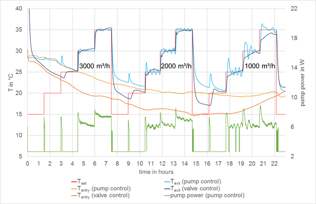
Figure 3. Comparison of valve and pump control (concept 3) for mixing circuit.
For the
energetic evaluation on yearly base, we used dynamic simulations with German
weather data [3] and focused on the cooler of our testing AHU with a constant
air volume flow of 3,000 m³/h. As illustrated in Figure 3, the throttling circuit with constant speed pump consumes 1,589 kWh/a,
followed by the internally pressure-controlled pump with savings of 30%.
Compared to this, our first concept could save around 64% and the second
concept with a smaller pump 76% (1,229 kWh) of pump energy. Using a
standard mixing circuit, we have the highest electric consumption of around 2,500 kWh
in around 2,050 annual operation hours per year, which is nearly the double of
the constant speed pump throttling circuit concept.
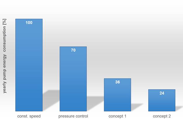
Figure 4.
Comparison of pump energy consumption for different concepts.
With our study we have pointed out problems of the state of the art of hydronic control concepts and demonstrated new control concepts for the hydronic circuits of AHUs, which save up to 76% of pump energy or increase control quality in our test cases. The shown simulated energy savings can even increase, as they strongly depend on profiles of demand-oriented ventilation and weather conditions. The control quality further depends on the dimensioning and operation of the AHU system. As the pumps in the analysed hydronic systems have medium modulation ratios of 4.6 and 3.7, we could even increase the control quality by preventing pulsing operation with pumps of higher ratios like the reheaters pump (with a ratio of 10). However, we have to consider the certain negative effects of poor control quality, which can even overcompensate pump energy savings.
In order to improve the control quality, we are going to publish further developed concepts, which focus particularly on this topic. This includes new concepts for run around coils.
We gratefully acknowledge our project partner WILO SE and the financial support by BMWi (German Federal Ministry of Economic Affairs and Energy), promotional reference 03ET1298A.
[1] Teichmann, J. et.
al: Reducing energy consumption of air handling units by optimized pump
control. Roomvent & Ventilation 2018, Helsinki;
06/2018.
[2] Roos, H.: Hydraulik der Warmwasserheizung. Oldenbourg Industrieverlag, pp 71, 138-1, 2002.
[3] TRY (2010), German Meteorological Service (Deutscher Wetterdienst): Dataset 2010, region 12.
Follow us on social media accounts to stay up to date with REHVA actualities
0