
Stay Informed
Follow us on social media accounts to stay up to date with REHVA actualities
This article is based on a paper presented at the 42nd AIVC - 10th TightVent & 8th venticool Conference “Ventilation Challenges in a Changing World” held on 5-6 October 2022 in Rotterdam, Netherlands.
|
Jirayut Sitthipuk |
School of Engineering and Built Environment, Edinburgh Napier University, Edinburgh, Scotland. |
The use of natural ventilation components as an enhancement for ventilation systems has become more desirable in the building sector. Mechanical ventilation systems are responsible for almost 40% of the total energy consumption. Applications of low carbon ventilation technologies, for example powerless ventilators, offer a prominent solution for reducing energy consumption in buildings. Powerless ventilators hold a potential to facilitate ventilation, reduce energy consumption and improve IAQ through the use of natural energy sources (Khan et al., 2008; Tan et al., 2016).
This study hypothesises the development of a new concept of home ventilation system that employs a wind driven turbine ventilator, as a means to reduce energy consumption and improve indoor air quality in a building. Additionally, the aim is to achieve a detailed understanding of the proposed system, in terms of ventilation performance for both air extraction and the supply of air by the turbine ventilator.
The model of a vertical wind turbine ventilator was created, as shown in Figure 1a, and consists of two parts: fresh air intake and turbine extractor. The principle of the turbine ventilator design was to provide active and passive ventilation through using the air intake vent for air supplying and the rotating turbine for extracting stale air. The study adopted Jadhav et al. (2016)’s CFD simulation approach of the wind tunnel domain setup for numerical simulations. The approach replicates the physical test rig for a wind tunnel. The whole computational domain is divided into two main regions: the flow domain and the chamber (see Figure 1b).
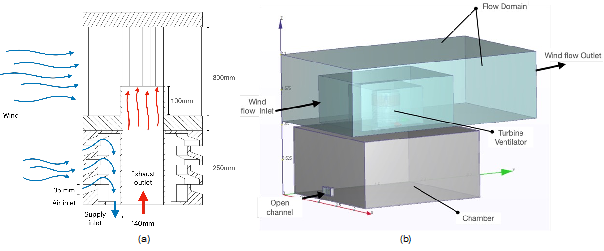
Figure 1. Schematic: (a) Turbine ventilator principle and (b) CFD computational domain setup.
Boundary conditions were assigned to each face of the computational domain. The entry of the computational domain upstream was defined as a uniform velocity-inlet boundary condition. The rotation of turbine ventilators started when the wind speed was higher than 2 m/s (Rimdžius et al., 2018). A pressure outlet boundary condition was assigned to the end of the domain downstream of the turbine ventilator, in which the pressure was set equal to 0. The k-epsilon turbulence model was used due to its robustness and proficiency in economically simulating a wide range of mean flow characteristics for turbulent flow conditions with reasonable accuracy (Jadhav et al., 2016).
The initial investigation was carried out by performing CFD simulations of the proposed model with two different blade profiles: 2 blades (2B-TV) and 8 blades (8B-TV). This allows us to quantify the influence of the turbine blade profile on the ventilation performance in terms of exhaust volume flow rate. The highlighted zones in Figure 2a indicate the influence on pressure distributions on the 2B-TV model. With the incoming flow on the convex side of the returning blade deflecting the rotation of the turbine ventilator, the highlighted region (the red circle shown in Figure 2a & 2b) is stagnant and creates a large pressure gradient on the blade convex (Tian et al., 2019). As a result, the flows started swirling in the middle region of the rotor, which creates a vortex, allowing the airflow to be influenced and therefore extracted from the duct (see Figure 2c)
.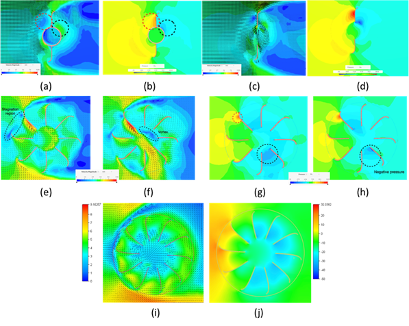
Figure 2. Velocity and pressure contours of 2B-TV, 8B-TV and modified 10B-TV.
On the other hand, the 8B-TV model exhibited better performance for developing the swirling flows, as shown in Figure 2e. The flows started entering the inner domain of the turbine ventilator from the top left corner and leaving through the bottom, causing the inner flows swirling in the interior of the turbine ventilator (see Figure 2f). Hence, the 8B-TV profile had a great impact on the swirling flow pattern, which leads to an increase in exhaust airflow rate. The CFD results of the 2B-TV and 8B-TV for air extraction performance were shown in Figure 3. It is noticeable that the 8B-TV greatly outperformed the 2B-TV by 66% beyond a wind speed above 2 m/s, which manages to meet the UK’s minimum requirement of air extraction rate with the extracted volume flow rate of 35.59 ℓ/s at wind speed of 3 m/s.
To further explore ventilation performance of the turbine ventilator, a decrease in blade height was considered in this study to determine the differences in performance of the turbine blades to be more efficient at a lower wind speed. Moreover, the number of blades was also increased for the modified model (10B-TV). Figure 2i shows that the flow behaviour was similar to the flow characteristics of the 8B-TV. However, in this case, the flows entered the inner domain from downstream as more inner flow swirled within the rotor. A vortex took place in the centre of the rotor domain as the flows started swirling. Despite the result of the modified 10B-TV exerting an exhaust airflow rate of 45.81 ℓ/s at 6 m/s, it still underperformed when compared to the 8B-TV model by approximately 50%, as shown in Figure 3.
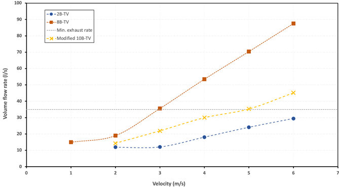
Figure 3. Comparison of air extraction performance between 2B-TV, 8B-TV and modified 10B-TV.
The performance on air supply rates was assessed against an induced flow rate entering through the air intake vent (AIV). The results of CFD simulations show the induced flows passing through the opening on the windward side of the channel (see Figure 4). Moreover, the recirculation zones were formed on the outer wall at lower edge of the louver bend (red circles in Figure 4a) after the airflow entered the inlet opening. This then develops the high-pressure area causing a loss in the air flow, which leads to a decreasing flow rate in the air supply channel. The CFD result of the volume flow rates induced by the AIV is shown in Figure 5, with the maximum flow rate of 38.25 ℓ/s at 6 m/s. In addition, it also meets the minimum ventilation rate for air supply of 25 ℓ/s when the wind speed is 5 m/s.
Features of the AIV profile were altered to further enhance its ventilation performance. Figure 4b shows that the size of the recirculation zones (in the red circles) of the modified AIV1 was reduced, which improved the ventilation performance by 5% compared to the AIV. In contrast, the modified AIV2 in Figure 4c outperformed the AIV by almost 20% due to an increase in an airflow rate of 48.11 ℓ/s at 6 m/s, with the results are compared in Figure 5.
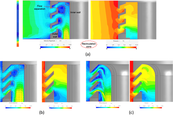
Figure 4. Velocity and pressure contours: (a) AIV, (b) modified AIV1 and (c) modified AIV2.
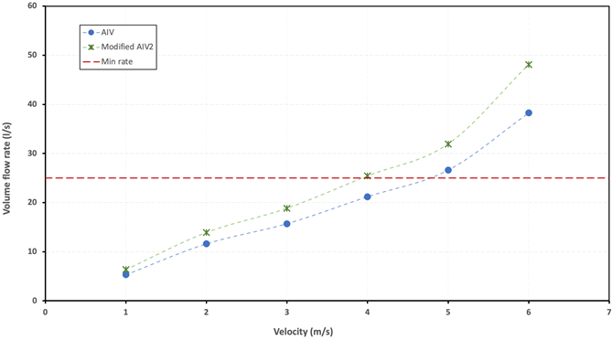
Figure 5. Comparison of ventilation performance for air supply between the AIV and modified AIV2.
The application of a powerless turbine ventilator to induce exhaust air flow rate through the roof is effective and efficient for the industrial building (Khan et al., 2008). However, it is deemed as unnecessary for domestic ventilation systems, mainly due to the required working environment, visual pollution for some homeowners and unreliable resources available for operation. It has been overlooked in ventilation strategies when compared to HVAC, but it is considered to be more efficient in terms of both energy saving and ventilation performance.
As the proposed turbine ventilator is a primary design, the study shows a promising potential for the proposed home ventilation system integrated with the turbine ventilator. With further improvements, this new concept of ventilation system could be a greener alternative for future home ventilation for new builds or conventional houses. It will be cheaper and greener for domestic dwellings if a new ventilation system integrated with a low carbon turbine ventilator that maximises a natural source of wind energy for ventilation and energy saving can be developed.
Jadhav GK, Ghanegaonkar PM and Garg S (2016) Experimental and CFD analysis of turbo ventilator. Journal of Building Engineering 6: 196-202.
Khan N, Su Y and Riffat SB (2008a) A review on wind driven ventilation techniques. Energy and Buildings 40(8): 1586-1604.
Rimdžius D, Bielskus J, Martinaitis V, et al. (2018) Experimental Evaluation of Turbine Ventilators Performance under Different Test Conditions. E3S Web of Conferences 64.
Tan YC, Ismail M and Ahmad MI (2016) Turbine Ventilator as Low Carbon Technology. Renewable Energy and Sustainable Technologies for Building and Environmental Applications. pp.167-174.
Tian W, Mao Z and Ding H (2019) Numerical study of a passive-pitch shield for the efficiency improvement of vertical axis wind turbines. Energy Conversion and Management 183: 732-745.
Follow us on social media accounts to stay up to date with REHVA actualities
0