


Stay Informed
Follow us on social media accounts to stay up to date with REHVA actualities
|
|
|
Martin Šimko | Dušan Petráš | Daniel Szabó |
Department of Building Services, Faculty of Civil Engineering, Slovak University of Technology, Bratislava, Slovakia | Department of Building Services, Faculty of Civil Engineering, Slovak University of Technology, Bratislava, Slovakia | Department of Building Construction, Faculty of Civil Engineering, Slovak University of Technology, Bratislava, Slovakia |
We live in a time when climate change is increasingly forcing us to deal with the question of the right choice of heating or cooling system for living spaces. Due to global warming, we are experiencing milder winter seasons and then, without a pleasant transitional period of spring, we find ourselves in hot summer days. The question of how to cool residential buildings during hot summer days therefore comes to the fore.
There are different choices of heating or cooling systems. One option for both heating and cooling design is the use of water-based radiant systems. Radiant systems are particularly suitable for combination with renewable sources, provide high sensible output and can be used for both heating and cooling [1,2,3].
Compared to other systems, large-area radiant systems provide a fundamentally more even distribution of temperatures indoors. In terms of design, radiant heating/cooling systems can be integrated into the wall, ceiling or floor. The common advantage of all three technical solutions is that they can be implemented as part of retrofitting, so they can be used in building renovation [4,5,6,7,8].
The laboratory consists of 3 office rooms of a north-east facing office building, with the same boundary conditions (Figure 1).
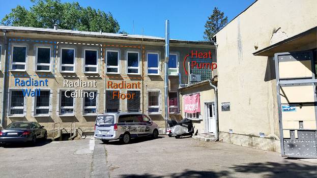
Figure 1. Office building with laboratory for testing radiant systems. (Author: Martin Šimko)
In the first office room number 202.1, a Siccus dry radiant floor system was installed in two circuits with 150 mm pipe spacing, using Comfort Pipe PLUS 14 × 2.0 mm, with a radiant area of 15 m². In the second room number 202.2, a Uponor Renovis dry radiant ceiling system using Uponor PE-Xa pipe 9.9 × 1.1 mm with 8 Uponor Renovis panels (2000 × 625 mm) was installed with a radiant area of 10 m². In the third office room number 203 a Uponor Renovis wall-mounted radiant system with Uponor PE-Xa 9.9 × 1.1 mm pipes with 8 Uponor Renovis panels (2000 × 625 mm) and a radiant area of 10 m² was installed. The heat and cooling source was an air-to-water heat pump F2040-6.
In Figure 2,is shown the floorplan of the office room number 202.1, where the radiant floor system was investigated.
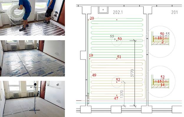
Figure 2. Floorplan of the room 202.1 with radiant floor system and placement of sensors. (Author: Martin Šimko, Uponor, s.r.o.)
Numbers 2, 14, 15, 18, 19, 20, 47, 49, 50, 51, 52 in Figure 2 represent the sensors type PT100 CRZ-2005-100-A-1-Ni and number 55 represents the heat flux sensor type FQA017CSI with accuracy within ±5% of the measured value. In the Figure 2, you can see also the installation of the Uponor Siccus dry floor system. The Figure 2 shows the building of the Uponor Siccus system board, the installation of the sensors, the installation of the Uponor comfort pipe plus 14 × 2,0 mm, the installation of the PE foil, the floor dry-screed board BRIO represented final layer of the radiant floor system and measured devices: globe thermometer, heat flux sensor, sensor of the surface temperature and data logger.
In Figure 3, on the right side, you can see the office room number 202.2, where the radiant ceiling system was investigated and on the left side in Figure 3 you can see the Uponor Renovis dry ceiling system. The placement of the sensors is shown on the right side in Figure 3. Numbers 3, 6, 7, 11, 12, 13, 41, 43, 44, 45, 46 represent the sensors type PT100 CRZ-2005-100-A-1-Ni and number 53 represents the heat flux sensor type FQA017C with accuracy within ±5% of the measured value.
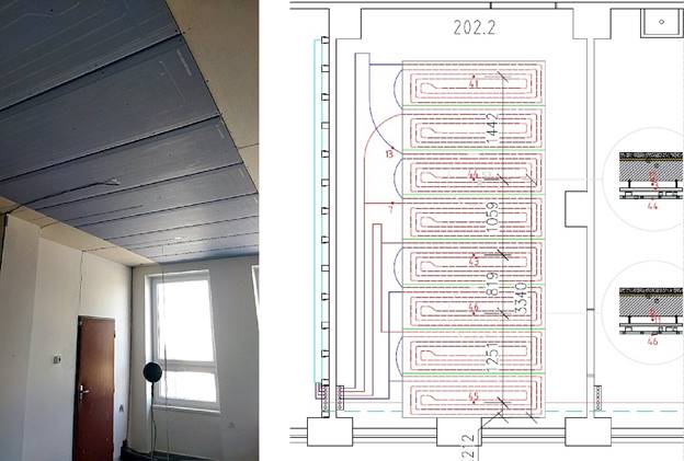
Figure 3. Floorplan of the room 202.2 with radiant ceiling system and placemant of sensors (Author: Martin Šimko, Uponor, s.r.o.)
In Figure 3, is shown the installation of Uponor Renovis radiant ceiling system.. The Uponor Renovis ceiling system is a dry ceiling system. The Uponor Renovis ceiling system consists from CD profiles for Uponor Renovis Panels with Uponor PE-Xa 9.9 × 1.1 mm pipes. We can also see the Tichelman loop with supply and return pipe for the Uponor Renovis Panels. In Figure 3, is shown the installation of the sensors (type PT100 CRZ-2005-100-A-1-Ni). In Figure 3, is shown the building of the final structure of the Uponor Renovis dry ceiling system. The Uponor Renovis ceiling system is a dry ceiling system and this system consists from 8 Uponor Renovis panels (2000 × 625 mm). The radiant area of the ceiling system is 10 m². The Figure 3 on the right shows the measurement equipment: globe thermometer, heat flux sensor, sensors of surface temperatures.
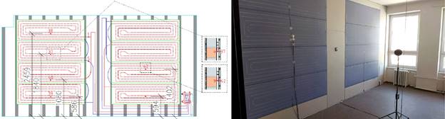
In Figure 4, is shown the section through the office room number 203, where the radiant wall system was investigated. On the right side in Figure 4 is shown the Uponor Renovis dry wall system. In Figure 4, is shown also placement of the sensors. Numbers 37, 38, 39, 40, 42 represent the sensors type PT100 CRZ-2005-100-A-1-Ni and number 54 represents the heat flux sensor type FQA017C with accuracy within ±5% of the measured value. In Figure 4, is shown also the building of the Uponor Renovis wall system. The Uponor Renovis wall system is dry wall system and this system consist from 8 Uponor Renovis panels (2000 × 625 mm). The radiant area of the wall system is 10 m². The Figure 4 from the left shows the Tichelmann loop with supply and return pipe for the Uponor Renovis Panels. The final structure of the Uponor Renovis wall radiant system consists of CD profiles with Uponor Renovis Panels.
![]()
![]() Figure 4. Radiant wall system and placement of sensors. (Author:
Martin Šimko, Uponor, s.r.o.)
Figure 4. Radiant wall system and placement of sensors. (Author:
Martin Šimko, Uponor, s.r.o.)
In Figure 4, we can see the final structure of the Uponor Renovis dry wall system and measurement equipment: globe thermometer, heat flux sensor, sensors of surface temperatures and data loggers
From 26.08.2022 to 01.09.2022 three radiant systems in cooling mode were verified. We verified the effect of radiant systems on the indoor climate. We investigated radiant dry floor system in office room 201.1, radiant ceiling system in office room 202.2 and radian dry wall system in office room 203. The effect of three radiant systems on the interior air were investigated for one week from 26.08.2022 to 02.09.2022. The thermal gradient was 15/19°C.
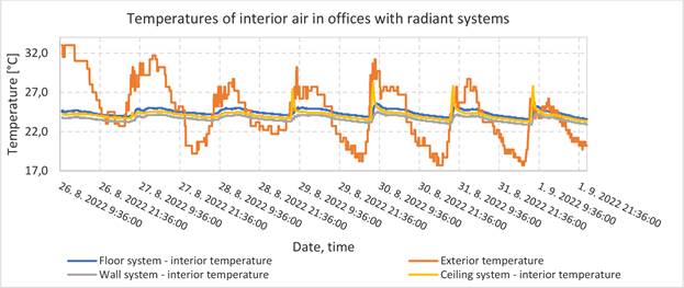
Figure 5. Relation between indoor and outdoor air temperature (Author: Martin Šimko)
Figure 5shows relation between indoor and outdoor air temperature in three office rooms with radiant systems from 26.08.2022 to 02.09.2022. We verified effects of the three radiant systems on the indoor climate (interior air) in three offices. The measurements of interior air were recorded with data loggers COMET U3430 and COMET S3120. The red curve represents the course of the outdoor air temperature, the blue curve represents the course of the indoor air temperature in the room 201.1 with radiant floor system, the yellow curve represents the course of the indoor air temperature in room 202.2 with radiant ceiling system, and the gray curve represents the course of the indoor air temperature in room 203 with radiant wall system. The results of the indoor air were measured using data loggers Comet U3430 in office rooms 201.1, 202.2 and the results of the indoor air in office room 203 were measured using data loggers Comet S3120. The maximum value of the outdoor air was measured on 26.08.2022 at 13:00, at that time the temperature of indoor air in office room 201.1 with radiant floor system was 24.6°C, the temperature of indoor air in office room 202.2 with radiant ceiling system was 23.8°C and the temperature of indoor air in office room 203 with radiant wall system was 24.2°C. The effect of the three radiant systems in cooling mode on the indoor climate of these offices in summer was sufficient. These results show that radiant systems can create a pleasant thermal comfort even in summer.
The paper shows the laboratory for testing of radiant floor, ceiling and wall systems. We explored the effect of three radiant systems in cooling mode on the indoor climate in summer. There is a significant potential of these three radiant systems to create a pleasing thermal comfort in summer. In terms of thermal comfort in cooling mode, radiant floor system was weaker than radiant wall or radiant ceiling. In future research it would be good to verify these three radiant systems: in terms of performance in both cooling and heating mode, how much energy does each radiant system consume individually, the temperature profile of each office in both cooling and heating mode, the surface temperatures of the radiant systems and the effect of the shading elements on the cooling performance of the three systems.
This research was supported by the Slovak Research and Development Agency under contract No. APVV-21-0144 and Ministry of Education, Science, Research, and Sport grants VEGA 1/0303/21 and 1/0304/21.
[1] J. Babiak, B.W. Olesen, D. Petráš. Low temperature heating and high temperature cooling. REHVA Guidebook No 7. 3rd revised ed. Brussels, Belgium: REHVA (2013).
[2] M. Krajčík, M. Arıcı, O. Šikula, M. Šimko, Review of water-based wall systems: Heating, cooling, and thermal barriers, Energy and Buildings. vol. 253 (2021).
[3] M. Krajčík, M. Šimko, O. Šikula, D. Szabó, D.Petráš, Thermal performance of a radiant wall heating and cooling system with pipes attached to thermally insulating bricks, Energy and Buildings. vol. 246 (2021).
[4] U. Akbulut, O. Kıncay, Z. Utlu. Analysis of a wall cooling system using a heat pump. Renew Energ 85 (2016).
[5] D. Petráš, M. Krajčík, J. Bugáň, E. Ďurišová. Indoor Environment and Energy Performance of Office Buildings Equipped with a Low Temperature Heating / High Temperature Cooling System. Adv Mater Res 899 (2014).
[6] X. Wu, L. Fang, B.W. Olesen, J. Zhao, F. Wang. Comparison of indoor air distribution and thermal environment for different combinations of radiant heating systems with mechanical ventilation systems. Building Serv. Eng. Res. Technol. 39 (2018).
[7] Á. Lakatos. Comprehensive thermal transmittance investigations carried out on opaque aerogel insulation blanket. Mater. Struct. 50 (2017).
[8] EN ISO 11855-2:2012. Building environment design - Design, dimensioning, installation and control of embedded radiant heating and cooling systems - Part 2: Determination of the design heating and cooling capacity.
Follow us on social media accounts to stay up to date with REHVA actualities
0