


Stay Informed
Follow us on social media accounts to stay up to date with REHVA actualities
|
|
|
Mete OgucUlus Yapi Tesisat Malzemeleri A.S. | Deniz HadzikurtesUlus Yapi Tesisat Malzemeleri A.S.deniz.hacikurtes@ulusyapi.com | Okan SeverUlus Yapi Tesisat Malzemeleri A.S.okan.sever@ulusyapi.com |
High rise multistory buildings involving
concrete and steel frames are embarked in many countries. Increase in sound
insulation performance requirements result in cost oriented and technically
practical solutions [1]. The most effective noise control measure is to locate
indoor technical rooms as far away as possible from noise-sensitive areas.
However, mechanical equipment rooms in high-rise multistory buildings are
typically located on intermediate floors, close to the occupied areas they
serve. In such cases, appropriate constructive layers should be selected for
walls, ceilings, and floors once the amount of noise is assessed within the
mechanical equipment rooms. For floorings, floating concrete floors are usually
required to separate mechanical spaces from noise-sensitive spaces that are
below the mechanical room [2].
Floating floor is a technical term which
implies that the flooring is separated from the structure so that it has no
rigid connection with surrounding building elements such as walls, floors and
columns. This is achieved by using various insulation materials such as rubber
mount isolators, resilient layers, flanking bands and strips. As a term,
floating floor may refer to various floor isolation methodologies that can be
adopted by using these products. Floorings raised on steel constructions in
data centers and laminate parquet floorings installed on resilient layers are
also called floating floors, but in our case we will be mostly dealing with
concrete slabs raised on rubber mounts or springs as used in most mechanical
rooms.
Insulation for the flooring in mechanical
spaces should be chosen according to the equipment type, equipment weight,
noise level and adjacent spaces intended purpose of use. Unnecessary and
overqualified insulation may result in excess amounts of investment costs. If
the main purpose of floor insulation is to overcome impact noise caused by the
machinery, then using vibration isolators, resilient layers or rubber pads is
probably a better choice since primary objective to install a floating floor
with resilient mounts and air cavity is to prevent airborne sound transmission.
Floating floors in mechanical rooms are
generally not designed as part of a vibration isolation scheme for plant
equipment. Floating floors with resilient mounts consist of concrete slab which
is completely disconnected from surrounding building elements by vertical
flanking strips to separate it from walls and columns, and resilient mounts to
support it above the structural floor. The resilient mounts chosen mostly
determine the overall impact noise isolation performance of the floating floor
application. Assuming an ideal condition in which flanking transmission are
neglected and there are no sound bridges, impact sound insulation improvement
can be calculated from equation (1).
 (1)
(1)
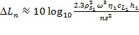
where ρs1 is the surface weight, η1 is the internal loss factor,
cL1 is the longitudinal wave
velocity, h1 is the thickness
of the floating slab, n is the number of resilient
mounts per unit area, and s is the stiffness of the
mounts used [3]. It is possible to achieve the same or even better impact sound
insulation performance with a similar floating floor construction by using a
resilient layer instead of rubber mounts. We can consider this case as a
locally reacting floating floor. Thus, we can use the following equations for
the calculation of improvement in impact noise insulation performance of a
floating floor with a resilient layer under ideal circumstances [3].
 (2)
(2)
where f is the
frequency. The natural frequency fo
of the system is
 (3)
(3)
where s is the
dynamic stiffness of the resilient layer and ρs1 is the surface weight of the
floating slab [3].
Comparing resilient mounts and resilient
layers impact noise performance from properties of the available products in
the market, it is clear that we can achieve similar impact noise performances
by choosing appropriate products according to their mechanical properties (Figure 1). Also,
vibration isolation products can be used when the foundation or base of a
vibrating machine is to be protected against large unbalanced forces or
impulsive forces [4]. However, resilient mounts and elastic underlays
performance vary a lot when we are dealing with airborne sound insulation. Even
when the so called impact noise, structural vibrations and flanking
transmissions are damped by vibration isolation, airborne noise transmission
can still be a problem.
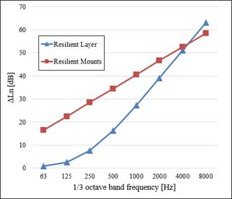
Figure 1. Comparison of improvement in impact
noise performances of floating floor systems constructed with a resilient layer
and rubber mounts.
The heavy equipment should be properly
supported to account for additional loads such as seismic loads [5]. Therefore,
heavy equipment such as a chiller is usually fastened to a housekeeping pad
which is anchored to the structural load bearing slab in floating floor
applications (Figure 2). It is possible to overcome impact noise and vibration
transmission caused by the machine by using an elastic or resilient member
between the machinery and the foundation. The problem is, it is usually
questioned whether the floating floor that surrounding the housekeeping pad is
doing any good in terms of acoustic insulation since its plinth base already
creates a short cut for airborne noise transmission through the cross section
of the plinth itself.
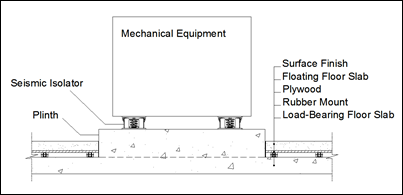
Figure 2. ASHRAE compatible floating floor
design for heavy equipment.
Floating floors and housekeeping pads have
different sound transmission losses. For the ease of our calculations we adopt
Goesel’s empirical method of double partitions to predict the floating floors
sound transmission loss [6]. Calculating the transmission loss of two
constituent single partitions RI
and RII assuming that
there are no structure-borne connections, and the gap is filled with porous
sound-absorbing material, the airborne sound transmission through the floating
floor can be calculated from equation (4).
![]() (4)
(4)
where ρo is the density and co is the speed of sound in air trapped in between the gap, s is the dynamic stiffness per unit area of the gap, d is the gap thickness, and RFF is the overall sound reduction performance of the
floating floor system.
To calculate isotropic single layered
structures sound reduction performances, calculation method described in EN
12354: Annex B is adopted [7]. Assuming that floating floor and plinth
structure are exposed to the same average sound intensity on the source side,
we can calculate the composite transmission loss from equation (5).
 (5)
(5)
where SFF is the surface area of floating floor system, SP is the surface area of the
plinth structure, and RP
is the sound transmission loss of plinth base structure.
We evaluate a mechanical room with the
equipment described above installed within. We consider a single rigid base of
plinth structure made of concrete with a height of 400 mm which is
surrounded by a floating concrete slab of 100 mm. Load-bearing concrete
slab has a 200 mm thickness as usual in most mechanical spaces and the air
gap between the floating slab and the load-bearing concrete slab is considered
to be 50 mm. Composite transmission loss is calculated according to the
method described for different surface area of housekeeping pad for a fixed
area of 200 m² mechanical space.
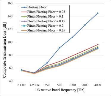
Figure 3. Change in composite transmission
loss for varying surface area of housekeeping pad to a fixed 200 m²
surface area of a floating floor system.
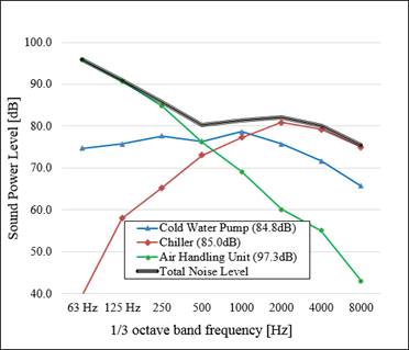
Figure 4. Sound power levels of cooling
equipment in a mechanical room.
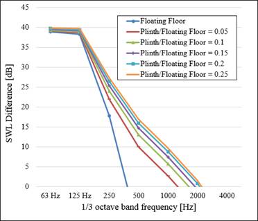
Figure 5. Insulation performance
comparison between various floating floor systems.
As it appears, there is a considerable
difference between the insulation performance of a whole floating floor and a
floating floor that encloses a housekeeping pad (Figure 3). However, once a rigid
base of plinth structure is built within a mechanical space, increasing the
surface area of the plinth base does not affect insulation performance in a
significant way. At this point, the question is whether the performance of
floating floors that enclose a plinth base structure is efficient under real
working conditions.
Most equipment manufacturers give single
value representations of their products noise levels. Unfortunately, we have to
work on broad band – or at least one-third octave band – responses of the
relevant machinery to design a working isolation system. Therefore, if it is
not possible to make measurements on site, having an archive of measurement
results of spectral noise levels of common machinery can be an advantage to
start with a reasonable design. As an example, we consider a cooling room with
a cold water pump, a chiller and an air handling unit (Figure 4). Even though spectral
noise characteristics of these three units vary, their combination gives us a
flatter response.
Assuming that the total noise within the
mechanical space is transmitted through the flooring to an adjacent space, the
difference between the total sound power level (SWL) of the equipment and the
composite transmission loss of flooring gives us an idea of sound insulation
performance of various floating floor systems with and without housekeeping
pads. As expected, having a monolithic floating floor is advantageous.
Existence of a housekeeping pad causes an increase in noise between 500 Hz
and 1 kHz. However, the change of housekeeping pad surface area does not
affect noise transmission dramatically (Figure 5).
The plinth structures contribution to
airborne sound insulation is investigated and with some simple calculations
available in literature it has been found that - for a realistic case - the
contribution of housekeeping pads to noise transmission is mostly in between
500 Hz and 1 kHz. Presence of a housekeeping pad causes a conspicuous
increase in noise transmission compared to a monolithic floating floor design.
However, if a floating floor design is made considering the equipment noise
levels from the beginning and appropriate slab thicknesses and insulation
materials are chosen, it is expected that the transmission loss should not vary
much according to the changing plinth base surface area. For future work,
further analysis and a more detailed model should be developed to investigate
floating floors with plinth base structures. It is recommended to investigate
more about such composite structures contribution to airborne and impact noise
transmission especially in mechanical spaces.
This project has been funded by Ulus Yapi
Tesisat Malzemeleri A.Ş.
[1] S.
Smith: Chapter 1: Profiling Existing and New Build Housing Stock, Building
Acoustics Throughout in Europe Volume 1: Towards a Common Framework in Building
Acoustics Throughout Europe, COST Action TU0901, 2014.
[2] J.
Lilly, A. Mitchell, B. Rockwood, S. Wise, ASHRAE Technical Commitees: 2011
ASHRAE Handbook - Heating, Ventilating, and Air-Conditioning Applications, SI
Edition, Chapter 48 – Noise and Vibration Control, American Society of Heating,
Refrigerating and Air-Conditioning Engineers, Inc., USA, 2011.
[3] I.
L. Ver, L. B. Beranek: Noise and Vibration Control Engineering. Wiley, USA,
2006.
[4] S.
S. Rao: Mechanical Vibrations. Pearson Prentice Hall, USA, 2004.
[5] J.R.
Tauby, R. J. Lloyd, T. Noce, J. T. F. M. Tunissen: ASHRAE: Practical Guide to
Seismic Restraint, American Society of Heating, Refrigerating and
Air-Conditioning Engineers, Inc., USA, 1999.
[6] K.
Goesele: Prediction of the Sound Transmission Loss of Double Partitions
(without Structureborne Connections), Acoustica, 45, 218-227, 1980.
[7] EN
12354-1:2000, Building Acoustics – Estimation of Acoustic Performance of
Buildings form the Performance of Elements: Part 1: Airborne Sound Insulation
Between Rooms, 2000.
Mechanical and electrical equipment rooms are one of the main sources of noise and vibration in buildings. In high-rise buildings, it is usually inevitable to locate equipment rooms in mid-floors rather than placing them far from noise sensitive areas such as basements or separate structures. The noise from the mechanical equipment such as chillers, circulation pumps, and air handling units in these spaces can travel via and through structure to adjacent occupant spaces. Structure-born noise from the machinery excitation transmitted as impact sound and vibration can be isolated by choosing proper vibration isolators. Yet, air-borne and flanking noise transmission from the flooring should still be carefully treated. Installing a floating floor provides high levels of air-borne and flanking sound reduction in such cases. A floating floor is either constructed by using an air gap or a resilient layer. Spring or rubber type mounts are utilized to provide an air gap. A composite sound transmission loss value for such types of floating floor applications are calculated and presented in this paper. Keywords: sound transmission, housekeeping pads, floating floors, sound insulation, equipment noise.
High rise multistory buildings involving concrete and steel frames are embarked in many countries. Increase in sound insulation performance requirements result in cost oriented and technically practical solutions [1]. The most effective noise control measure is to locate indoor technical rooms as far away as possible from noise-sensitive areas. However, mechanical equipment rooms in highrise multistory buildings are typically located on intermediate floors, close to the occupied areas they serve. In such cases, appropriate constructive layers should be selected for walls, ceilings, and floors once the amount of noise is assessed within the mechanical equipment rooms. For floorings, floating concrete floors are usually required to separate mechanical spaces from noise-sensitive spaces that are below the mechanical room
Follow us on social media accounts to stay up to date with REHVA actualities
0