


Stay Informed
Follow us on social media accounts to stay up to date with REHVA actualities
Olof Andersson | Niklas Håkansson | Leif Rydell |
PhD/Adj. prof – former Sen. consultant at Sweco ABGeostrata HBolle.geothermal@hotmail.com | Operations engineerXylem Water Solutionsniklas.hakansson@xyleminc.com | Sen. Consultant – former Operations engineer at Xylem Water SolutionsReikab ABleif.rydell61@gmail.com |
Already in 2010, Xylem (formerly Flygt) in Emmaboda commissioned a high temperature storage facility for the recovery of waste heat. The storage was designed for charging 3.6 GWh of waste heat in the summer of which 2.2 GWh was estimated to be recovered for space heating during the winter. The storage working temperature was expected to be between +60 and +40°C. The objective with the BTES was to replace a significant amount of purchased district heating, see Figure 1.
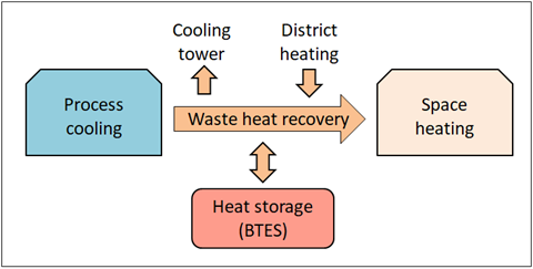
Figure 1. Xylem's system for heat recovery based on process cooling includes heat storage (BTES) for seasonal storage of waste heat. The storage reduces disposal of waste heat through the cooling tower for cooling and purchased district heat for space heating.
In the first years of operation, it was found that the expected high temperature waste heat quantity was not sufficient. Therefore, a number of measures were taken to also capture low-grade waste heat. As an example, a heat pump was installed for the foundry's ventilation system, which in the process acts as a climate cooling in this otherwise warm workplace. The measures allowed more and more heat to be recovered both directly and for storage. In 2014, storage capacity was basically reached. By this time, about 10 GWh had been loaded into the storage, raising the temperature to just over 40°C. Over the next three years, the temperature stabilized to a maximum of 45°C, despite the fact that the availability of waste heat remained high. The reason was that a large part of the stored heat spread sideways, which in turn led to increased storage losses. Thus, the temperature in the storage did not become high enough to be directly used for space heating. As a result, only about 10% of the stored heat was recovered the years 2015–2017. Thus, in order for the storage to survive, a reinforced heat extraction capacity was needed, in this case with a heat pump system. This solution was recommended in a scientific follow-up report that studied the general function of the plant [1].
The storage consists of 140 boreholes, 150 m deep and with a c/c-distance of 4 m. It is located on a flat grass surface just outside the factory area and has a rectangular shape measuring 60 × 40 m. It was constructed during the winter of 2009–2010.
The borehole heat exchangers are of a coaxial type consisting of double pipes with intermediate insulation in lengths of 10 m. One of the advantages of this type of heat exchanger is that it allows for bidirectional flow. Thus, the highest storage temperature can always be located at the bottom of the storage. Another advantage is that the thermal resistance is significantly less compared to a conventional U-pipe. The latter option usually has thermal resistance around 0.08 K(W/m). The resistance of the coaxial heat exchanger was measured at 0.02, thus four times more efficient.
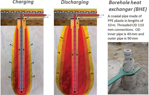
Figure 2. System with coaxial borehole heat exchanger with dual flow function. The flow is reversed when discharged compared to charging. Thus, the temperature is always warmest at the bottom of the storage, which reduces heat losses and provides the highest possible temperature at extraction of heat.
The boreholes are divided into seven sections (A-G) with 20 holes in each, see Figure 3. The three inner sections are thought to have the highest temperature and the four outer ones to act as a buffer zone with slightly lower temperatures. The idea behind this lay-out is to adjust the extraction temperature to fit the demand. To achieve this function control valves are placed on the assembly pipes in the storage central, as shown in the figure.
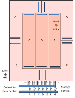
Figure 3. The design of the borehole storage with seven sections (A-F). Each section has 20 boreholes of which two are in series. The boreholes are connected with OD 40 pipes, and ends up to OD 90 field manifolds at both section ends (blue). Finally, the field manifolds connect to larger manifolds in the storage central. MW: monitoring wells. GT: temperature sensors
It took a few years to get the decision through, but in September 2018, a heat pump system was ready for commissioning. This consists of 8 parallel connected real estate heat pumps (Nibe F1345-60). The evaporator side connects to the supply and return pipes of the storage and the condenser side connects to the internal heating grid, see Figure 4. The warm temperature on the evaporator side allows the system to deliver significantly higher capacity than the nominal, in the current case up to 800 kW. The heat pumps together with the direct recycling can handle the heat demand down to about −5 degrees outside temperature. At lower outdoor temperatures, the external district heating enters for peak shaving.
The horizontal piping system of the storage is embedded in about 30 cm of sand, after which there is a 40 cm thick layer of insulating foam glass, followed by about 30 cm of topsoil. The insulating ability is measured with temperature sensors under and above the foam glass and in the upper part of the topsoil. For measuring the storage temperature there are two monitoring wells (MW), one inside and one a few meters outside the storage. In these wells temperature sensors are installed (GT1-3 in Figure 3). Furthermore, supply and return temperatures to and from each of the sections are measured, as well as the pressure in the two assembly pipes in the storage central.
From the main technical central, about 200 m from the storage, the heat carrier is circulated via a culvert using a frequency-controlled circulation pump designed for a maximum flow of 21 ℓ/s (3 ℓ/s and section). Heat is supplied or collected from the storage via a heat exchanger (HEX) that on the secondary side is connected to Xylem's internal heating grid. In the system there are sensors for instantaneous measurement of temperatures, flow and pressure, see Figure 4. In addition, electricity consumption for the heat pumps and the circulation pumps each side of the HEX in order to calculate the system SPF.
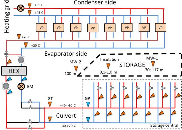
Figure 4. Simplified flowchart for heat extraction with sensors for energy measurement (EM), system pressure (GP) and temperatures (GT). In addition, electricity consumption is measured for heat pumps and circulation pumps.
The system performance is monitored in an international research project, IEA HPT Annex 52 “Long-term measurements of GSHP system performance in commercial, institutional and multi-family buildings” where Xylem's plant is one of some 40 shallow geothermal installations and the only one associated with an industry. Operational data is now available after three full winter seasons with the heat pumps. As shown in Figure 5, the accumulated heat extraction from the storage has drastically increased compared to former years.
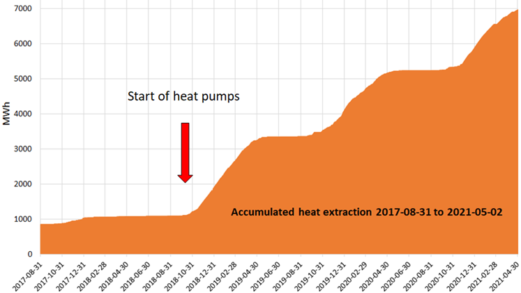
Figure 5. The accumulated heat extraction from the storage in the last five years.
The higher withdrawal of heat in the last three years has gradually reduced the temperature in the storage down to approx. +25°C at the end of the heating season. As a result, the temperature gradient between the storage center and the boundary has decreased, which means that the lateral heat flow has more or less ceased, see Figure 6.
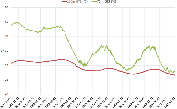
Figure 6. Temperature development inside the storage (GT1) and just outside (GT3) in the last five years.
The lowered average temperature of the storage, with the target to work at 40/20°C, also entails a number of other advantages, of which the following are tangible.
· The storage system has a significantly higher cooling capacity during the summer, which in turn means that more heat can be stored with reduced cooling tower operation as a result.
· Reduced heat losses due to less lateral flow of stored heat.
· Heat pumps for the recovery of low-grade waste heat can be operated with a lower condensation temperature and thus higher COP.
· Reduced risks of technical problems in the storage heat carrier loop, which means reduced potential for circulation pump cavitation, degassing of the heat carrier and clogging of pipes and the heat exchanger.
The investment cost of the original system was in total approx. SEK 12.5 million, of which 30% was received as a state contribution. The assessment was that the investment would be repaid after 5–6 years. It was then assumed that some 2,000 MWh/year of purchased district heating could be replaced by stored waste heat. That turned out not be the case. Only 1,200 MWh of recovered heat between 2014 and 2017 was far from enough. On the other hand, the storage concept led to a strengthened utilization of low-grade waste heat carried out during the years 2011–14. These were in themselves profitable in that the direct heat recovery during the winter could be doubled to about 7,000 MWh/year (2020).
A bonus is that the foundry has received climate cooling and that the amount of purchased city water for cooling in chilling pools has decreased significantly. Furthermore, the operating and maintenance costs of the cooling tower have decreased as a result of the increased waste heat use. However, the value of these benefits has not yet been priced.
The additional investment in the new heat pump system to amounted to about SEK 2.5 million. During the first three years of operation, a total of 6,500 MWh of heat has been produced by using 1,440 MWh of electricity for running the system. This ends up with a seasonal performance factor (SPF) of 4.5, thus saving around 78% of energy. The value of the savings with the energy prices currently applicable to Xylem is approximately SEK 3.8 million. Hence, the investment in the new heat pump system is more than repaid after three heating seasons.
In general, this type of BTES tends to be overestimated in terms of temperature at recovery of the stored heat. Our assessment is that a heat pump system is needed to be able to make full use of the storage. It is possible that a HT-BTES can work with heat exchange alone, but the temperature when charging must then be kept significantly higher than that reached during discharge.
Technically, it is not a problem to construct a HT-BTES in almost any geological formation, but the investment cost is rather high. However, since the life span is long (>50 years), the investment can be written off for a long time. Since the stored waste heat is basically free, there is great potential to create storages with a high profitability, including the cost of helping heat pumps when discharged.
In the Emmaboda case, the investment in coaxial borehole heat exchangers has helped to obtain a thermally favorable temperature profile in the storage. However, this advantage has not been sufficient to prolong a high temperature when extracting the heat. The recommendation is therefore to use conventional borehole heat exchangers (thermal resistant U-pipes) in a fully closed loop to avoid various technical problems, such as vacuum pressure and stripping of gas. In Emmaboda, this problem has been a major concern, especially in the early years of operation. To our opinion it is better to accept a less efficient borehole heat exchanger and compensate this choice with a heat pump solution for an efficient recovery of the stored heat.
This article is prepared within the scope of IEA HPT Annex 52 witch has been has funded by Energimyndigheten (Swedish Energy Agency), Geostrata HB, Reikab AB, and Xylem Water Solutions.
[1] Nordell, B., Liuzzo Scorpio, A., Andersson, O. Rydell, L., Carlsson, B. 2016. “The HT BTES plant in Emmaboda. Operation and experiences 2010-2015”. Div. of Architecture and Water, Luleå University of Technology, January 2016.
Follow us on social media accounts to stay up to date with REHVA actualities
0