


Stay Informed
Follow us on social media accounts to stay up to date with REHVA actualities

Copyright ©2022 by the authors. This conference paper is published under a CC-BY-4.0 license. |
|
|
|
|
|
Francisco CominoDepartamento de Mecánica, Escuela Politécnica Superior, Universidad de Córdoba, España, francisco.comino@uco.es | Jesús Castillo-GonzálezCentro Tecnologico del Plastico Andaltec, Jaén, España | Francisco J. Navas-MartosCentro Tecnologico del Plastico Andaltec, Jaén, España | Pablo E. RomeroDepartamento de Mecánica, Escuela Politécnica Superior, Universidad de Córdoba, España, | Manuel Ruiz de AdanaDepartamento de Química-Física y Termodinámica Aplicada, Escuela Politécnica Superior, Universidad de Córdoba, España |
Evaporative cooling units are an effective alternative to conventional air conditioning technologies, due to their high efficiency and reduced primary energy consumption. There are two main types of evaporative cooling systems: the direct evaporative cooling (DEC) system, and the indirect evaporative cooling (IEC) system. DEC is based on direct contact between air and water, while IEC is based on heat and mass transfer between two flows of air, separated by a heat transfer surface with a dry side, where only air is cooled, and a wet side, where water is evaporated into air. The main objective of the present work was to design and manufacture a highly compact indirect evaporative cooler. Firstly, a mathematical model based on ε-NTU numerical method to determine the optimal geometrical and operating parameters of an IEC system was developed. The mathematical model allowed to obtain the temperature, enthalpy and humidity distributions of the air inside the exchanger. Then, the air-cooling system was manufactured. The device consisted of a compact heat and mass exchanger, a water distributing system and an outer casing. Finally, the IEC system was studied experimentally. An experimental facility was designed to study these air-cooling systems. The cooling unit performance indicators were the cooling capacity per unit volume and per unit airflow rate. The experimental results showed that the cooling capacity per unit volume of the device was 177 kW/m³, and the cooling capacity per unit airflow rate was 10.9 kW/(m³/s). These results suggested that highly compact indirect evaporative coolers can achieve air-cooling processes with a low energy consumption and a low environmental impact.
European Union directives reinforced the objective of reducing primary energy consumption and the integration of renewable energies in buildings, instead of using fossil fuels [1]. A large percentage of current energy consumption and CO₂ emissions are due to heating, ventilating and air conditioning, HVAC, systems.
A traditional method widely used in air cooling is that of conventional HVAC systems based on direct expansion units [2]. However, direct expansion systems typically use refrigerant gases, which could emit polluting gases into the atmosphere, and in addition, they depend mainly on electrical energy.
Another air-cooling technology is evaporative cooling. The evaporative cooling units are based on heat and mass transfer between air and cool water [3]. There are two main types of evaporative cooling systems: the direct evaporative cooling, DEC, system and the indirect evaporative cooling, IEC, system. DEC is based on direct contact between air and water, while IEC is based on heat and mass transfer between two flows of air, separated by a heat transfer surface with a dry side, where only air is cooling, and a wet side, where water is evaporated into air [4]. In addition, there are different types of IEC [4]: conventional IEC, which supply air between the dry bulb temperature and the wet bulb temperature; dew-point evaporative cooler (DIEC), including single-stage counter-flow, and finally, Maisotsenko-cycle (MIEC), including multi-stage cross-flow. The last two supply air between the dry bulb temperature and the dew point temperature.
One of the most effective indirect evaporative cooling solutions are the dew-point counter-flow cycles, DIEC, [5]. The DIEC systems have been studied for many applications [6]. A DIEC with a direct expansion system applied to a residential building in China showed high potential for energy savings [7], up to 39% compared to a direct expansion system. DIEC systems were combined with desiccant systems [8–10], managing to control temperature and humidity independently.
IEC systems have been widely analysed by many authors in the available literature [11,12], in particular focusing on the analysis of influential parameters on outlet air conditions, such as inlet air temperature, inlet air humidity. The coefficient of performance of IEC systems was analysed for different operating conditions, evaluating the effect of variable inlet air velocities [13]. The amount of water flow rate was also analysed [14], which has a significant effect on system performance. The influence of the exchanger material was studied in other works [15].
The design of IEC systems was also analysed in recent works to improve their thermal behaviour. The cooling power of a DIEC system with different number of perforations between the dry and wet channels was analysed [16]. The results showed that the configuration with a single air passage increased the cooling power compared to configurations with four air passages. In another work, a mathematical model of DIEC was developed with different numbers of air passages. [17]. Two DIEC systems with cross flow configuration, one with fins and one without fins, were developed and analysed under different inlet air conditions [18]. The DIEC system with fins improved thermal performance up to 40% compared to the same system without fins. An optimization study of a DIEC unit with counter-flow configuration was developed [19]. The goal of the study was to increase the performance of the system by varying the air speed, the flow rate and the length and height of the channels. A DIEC with counter-flow configuration was manufactured from the results obtained of an optimal design with a mathematical model [20]. The energy performance of this system increased up to 19%.
Therefore, managing air with an efficient air-cooling unit, such as IEC systems, which does not depend mainly on electrical energy and does not use any refrigerant, could be an interesting alternative to conventional air-cooling units based on vapor- compression cycles. The main advantages of evaporative coolers are their constructive simplicity and high efficiency.
The main objective of the present work was to design and manufacture a highly compact indirect evaporative cooler. The cooling unit performance indicators were the cooling capacity per unit volume and per unit airflow rate. Firstly, a mathematical model based on modified ε-NTU numerical method to determine the operating parameters and optimal geometrical of an IEC was developed. Then, the air- cooling system was manufactured.
The steps followed to develop the IEC system were as follows: (i) an IEC design was carried out and the ε- NTU mathematical model was applied to the IEC design; (ii) the numerical results were analysed; and (iii) the IEC system was manufactured.
In the present work was designed an IEC system to handle air in small spaces. The air-cooling device consisted of a compact heat and mass exchanger, a water distributing system and an outer casing.
The heat and mass exchanger was designed with a counter-flow configuration. The air handling process consisted of an inlet air flow, which circulates through dry channels, exchanging heat with the attached channels, see Figure 1. The inlet air stream was divided into two air streams at the end of the device, one air stream was recirculated in the inverse direction through wet channels, exchanging heat and mass between air and water, and another stream was supplied, see Figure 1. Water only enters wet channels, so the supply air stream was cooled without varying its moisture content.
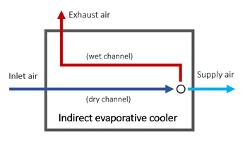
Figure 1. Diagram of the air flows of an IEC system.
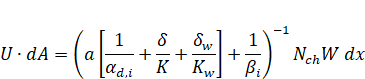
A mathematical model of IEC systems was developed to study the energy performance of an IEC system. This model was based on ε-NTU numerical method. The main equations of the model are expressed by (1)-(3).
| (1) |
| (2) |
| (3) |
Where NTU is number of transfer units; U is overall heat transfer coefficient [W·m⁻²·K⁻¹]; A is area [m²]; C is heat capacity rate [kg·s⁻¹]; a is slope of the temperature-enthalpy saturation line [kJ·kg⁻¹·K⁻¹]; δ is thickness of plates [m]; δw is thickness of water film [m]; αd,i is; K is thermal conductivity of wall [W·m⁻¹·K⁻¹]; Kw is thermal conductivity of water film [W·m⁻¹·K⁻¹]; βi is mass transfer coefficient for water vapor [kg·s⁻¹·m⁻²]; Nch is number of channels; W is width of the exchanger [m]; x is distance of sub-heat exchanger [m]; ε is effectiveness.
The IEC mathematical model developed allows to determine the optimal geometrical and operating parameters. The IEC mathematical model was implemented in Engineering Equation Solver (EES) software.
The heat and mass exchanger of the IEC system was manufactured by using 3D printing techniques. 3D printing can be used to manufacture complex design prototypes at a low economical cost. However, the main limitation of this manufacturing technique could be the size of the prototypes.
A design of the manufactured IEC system is shown in Figure 2. It can be observed the heat and mass exchanger, a reservoir for water and adapter parts for testing the IEC system. The water distribution was carried out through perforations in the upper part of the device. The driven water came from the network. The exchanger was made up of 12 dry channels and 11 wet channels. The dimensions of the exchanger were 130 mm high, 140 mm long and 116 mm wide, and the material used to make the exchanger was resin [21].
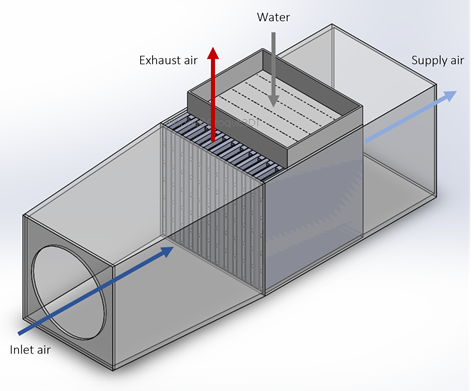
Figure 2. Design of the IEC system.
The design of a dry channel of the IEC system is shown in Figure 3.
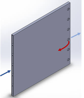
Figure 3. Design of the dry channels.
The thickness of the walls was 0.9 mm. These channels were composed of 6 perforations with a diameter of 5 mm. In addition, the wet channels were covered with a thin layer of cotton in order to retain the maximum amount of water.
The performance of the IEC system designed was evaluated under the following ratios:
· Cooling capacity per unit volume of the IEC system, see Eq. (4).
| (4) |
· Cooling capacity per unit airflow rate of the IEC system, see Eq. (5).
| (5) |
Where Qcooling was computed with energy balance on the dry-side fluid, see Eq. (6).
| (6) |
Some commercial IEC systems obtained values of CV and CR of 5.1 kW/m³ and 23.5 kW/(m³/s), respectively [22].
A test facility was used to analyse the experimental performance of the IEC system under different inlet air temperatures, from 27°C to 46°C, and different inlet air flow rate, from 100 m³/h to 190 m³/h. The supply air flow rates were 75 m³/h for the inlet air flow rate of 100 m³/h and 115 m³/h for the inlet air flow rate of 190 m³/h. The value of inlet humidity ratio remained constant, 10 g/kg.
All the experimental tests were carried out under steady-state conditions. The sampling time was 3 seconds, and the values are averaged every 30 min. The accuracy of the measuring devices used was ±0.12°C for the temperature sensors, ±0.15°C for the dew-point temperature sensors and ±0.5% for the differential pressure transmitters.
The energy consumption of a fan to overcome the pressure losses of the heat exchanger was calculated with the values of friction losses and minor losses.
The numerical and experimental results of the manufactured IEC system are shown in this section.
The mathematical model can be individually applied to n sub-heat exchangers of an IEC system. For the present work, 60 sub-heat exchangers were considered. As an example, the air conditions of the dry and wet air streams for each computational element of the exchanger are shown in Figure 4. This model allowed to obtain the temperature, enthalpy, and humidity distributions of the air inside the exchanger. Moreover, this mathematical model could be used to obtain the length of the heat and mass exchanger from pre-established inlet and outlet air conditions.
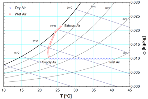
Figure 4. Psychrometric chart with the dry and wet air streams for each computational element.
The result of the manufacture of the heat and mass exchanger of the IEC system is shown in Figure 5. It can be observed that the exchanger was stacked using dry and wet channels. The wet channels were covered with a thin layer of cotton in order to retain water, which was supplied from the top.
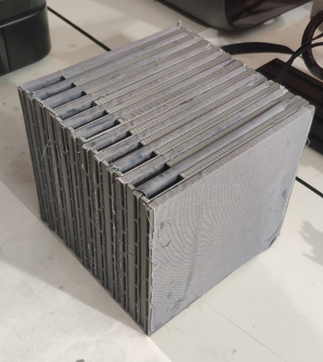
Figure 5. Heat and mass exchanger of the IEC system.
The experimental results of CV and CR for each case study are shown in Figure 6 and Figure 7. It can be observed than the CV values increased when the inlet air temperature was raised, see Figure 6. The IEC system also improved the CV value when the inlet air flow rate increased from 100 m³/h to 190 m³/h, as shown in Figure 6. The maximum CV value was 177 kW/m³ for an inlet air temperature of 46°C and an inlet air flow rate of 190 m³/h. However, the minimum CV value was 45 kW/m³ for an inlet air temperature of 27°C and an inlet air flow rate of 100 m³/h. Therefore, the air-cooling device increased its cooling capacity for hot inlet air conditions and higher air flow rate.
The CV values obtained in the present work were significantly higher than those obtained by commercial IEC systems, shown in section 2.4. Therefore, the device was designed and manufactured with high compactness.
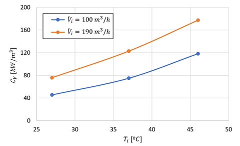
Figure 6. Results of cooling capacity per unit volume of the IEC system.
Regarding CR, similar trends to those obtained for CV were found when the inlet air temperature increased. That is, the higher the air temperature, the higher the CR value, as shown in Figure 7. However, CR decreased when the inlet air flow rate increased. The maximum CR value was 14.51 kW/(m³/s) for an inlet air temperature of 46°C and an inlet air flow rate of 100 m³/h, and the minimum CR value was 5 kW/(m³/s) for an inlet air temperature of 27°C and an inlet air flow rate of 190 m³/h. For this ratio, the CR values obtained in the present work were lower than those obtained by commercial IEC systems, shown in section 2.4. Therefore, the device needed to supply less flow to cool air.

Figure 7. Results of cooling capacity per unit airflow rate of the IEC system.
In the present work, the geometric design and manufacture of an indirect evaporative cooling (IEC) system was carried out.
The design of the IEC system was achieved from numerical results obtained with a mathematical model based on ε-NTU numerical method. Moreover, this model allowed to obtain the temperature, enthalpy, and humidity distributions of the air inside the IEC system.
The experimental performance of the air-cooling device was evaluated under two ratios: cooling capacity per unit volume (CV) and cooling capacity per unit airflow rate (CR). The results showed high CV values, up to 177 kW/m³, mainly for high inlet air temperatures and inlet air flow rates. The CR results were higher for high inlet air temperatures and low inlet air flow rates, with a maximum value of 10.9 kW/(m³/s).
These results suggested that highly compact indirect evaporative coolers can achieve air-cooling processes with a low energy consumption and a low environmental impact.
The authors acknowledge the financial support received by the European Regional Development Fund and the Andalusian Economy, Knowledge, Enterprise and University Council, Spain, through the research project HICOOL, reference 1263034, and by European Union's Horizon 2020 research and innovation programme, through the research project WEDISTRICT, reference H2020-WIDESPREAD2018-03-857801. The present work has also been conducted as a part of the CLIMASEE project 12020113 funded by Diputación Provincial de Jaén.
The datasets generated during and/or analysed during the current study are not available because the authors continue to investigate the air-cooling system, but the authors will make every reasonable effort to publish them in near future.
[1] European Parliament, European Directive 2010/31/EU on the Energy Performance of Buildings, 2010. doi:doi:10.3000/17252555.L_2010.153.eng.
[2] P. Sun, J.Y. Wu, R.Z. Wang, Y.X. Xu, Analysis of indoor environmental conditions and heat pump energy supply systems in indoor swimming pools, Energy Build. 43 (2011) 1071–1080. doi:10.1016/j.enbuild.2010.08.004.
[3] B. Porumb, P. Ungureşan, L.F. Tutunaru, A. Şerban, M. BǍlan, A Review of Indirect Evaporative Cooling Operating Conditions and Performances, Energy Procedia. 85 (2016) 452–460. doi:10.1016/j.egypro.2015.12.226.
[4] B. Porumb, P. Ungureşan, L.F. Tutunaru, A. Şerban, M. BǍlan, A Review of Indirect Evaporative Cooling Technology, Energy Procedia. 85 (2016) 461–471. doi:10.1016/j.egypro.2015.12.228.
[5] H. Sadighi Dizaji, E.J. Hu, L. Chen, A comprehensive review of the Maisotsenko-cycle based air conditioning systems, Energy. 156 (2018) 725–749. doi:10.1016/j.energy.2018.05.086.
[6] M.H. Mahmood, M. Sultan, T. Miyazaki, S. Koyama, V.S. Maisotsenko, Overview of the Maisotsenko cycle – A way towards dew point evaporative cooling, Renew. Sustain. Energy Rev. 66 (2016) 537–555. doi:10.1016/j.rser.2016.08.022.
[7] Z. Duan, X. Zhao, J. Liu, Q. Zhang, Dynamic simulation of a hybrid dew point evaporative cooler and vapour compression refrigerated system for a building using EnergyPlus, J. Build. Eng. 21 (2019) 287–301. doi:10.1016/j.jobe.2018.10.028.
[8] S. Delfani, M. Karami, Transient simulation of solar desiccant/M-Cycle cooling systems in three different climatic conditions, J. Build. Eng. 29 (2020) 101152. doi:10.1016/j.jobe.2019.101152.
[9] F. Comino, J. Castillo González, F.J. Navas- Martos, M. Ruiz de Adana, Experimental energy performance assessment of a solar desiccant cooling system in Southern Europe climates, Appl. Therm. Eng. 165 (2020) 114579. doi:10.1016/j.applthermaleng.2019.1145 79.
[10] F. Comino, M. Ruiz de Adana, F. Peci, Energy saving potential of a hybrid HVAC system with a desiccant wheel activated at low temperatures and an indirect evaporative cooler in handling air in buildings with high latent loads, Appl. Therm. Eng. 131 (2018) 412–427. doi:10.1016/j.applthermaleng.2017.12.00 4.
[11] D. Pandelidis, S. Anisimov, P. Drag, Performance comparison between selected evaporative air coolers, Energies. 10 (2017) 1–20. doi:10.3390/en10040577.
[12] F. Comino, S. Milani, S. De Antonellis, C.M. Joppolo, M. Ruiz de Adana, Simplified performance correlation of an indirect evaporative cooling system: development and validation, Int. J. Refrig. 88 (2018) 307–317. doi:10.1016/j.ijrefrig.2018.02.002.
[13] A. Ahmad, S. Rehman, L.M. Al-Hadhrami, Performance evaluation of an indirect evaporative cooler under controlled environmental conditions, Energy Build. 62 (2013) 278–285. doi:10.1016/j.enbuild.2013.03.013.
[14] S. De Antonellis, C.M. Joppolo, P. Liberati, S. Milani, L. Molinaroli, Experimental analysis of a cross flow indirect evaporative cooling system, Energy Build. 121 (2016) 130–138. doi:10.1016/j.enbuild.2016.03.076.
[15] A. Tejero-González, M. Andrés-Chicote, E. Velasco-Gómez, F.J. Rey-Martínez, Influence of constructive parameters on the performance of two indirect evaporative cooler prototypes, Appl. Therm. Eng. 51 (2013) 1017–1025. doi:10.1016/j.applthermaleng.2012.10.05 4.
[16] S.J. Oh, M.W. Shahzad, M. Burhan, W. Chun, C. Kian Jon, M. KumJa, K.C. Ng, Approaches to energy efficiency in air conditioning: A comparative study on purge configurations for indirect evaporative cooling, Energy. 168 (2019) 505–515. doi:10.1016/j.energy.2018.11.077.
[17] H. Sadighi Dizaji, E.J. Hu, L. Chen, S. Pourhedayat, Development and validation of an analytical model for perforated (multi-stage) regenerative M-cycle air cooler, Appl. Energy. 228 (2018) 2176– 2194. doi:10.1016/j.apenergy.2018.07.018.
[18] M. Ali, W. Ahmad, N.A. Sheikh, H. Ali, R. Kousar, T. ur Rashid, Performance enhancement of a cross flow dew point indirect evaporative cooler with circular finned channel geometry, J. Build. Eng. (2020) 101980. doi:10.1016/j.jobe.2020.101980.
[19] J. Lin, R. Wang, C. Li, S. Wang, J. Long, K.J. Chua, Towards a thermodynamically favorable dew point evaporative cooler via optimization, Energy Convers. Manag. 203 (2020) 112224. doi:10.1016/j.enconman.2019.112224.
[20] Z. Duan, X. Zhao, J. Li, Design, fabrication and performance evaluation of a compact regenerative evaporative cooler: Towards low energy cooling for buildings, Energy. 140 (2017) 506–519. doi:10.1016/j.energy.2017.08.110.
[21] Formlabs, https://formlabs.com/materials/, (Accessed 10.12.21). (2021).
[22] Climate Wizard by Seeley International, Indirect Evaporative Air Conditioning, (2021).
Follow us on social media accounts to stay up to date with REHVA actualities
0