

Stay Informed
Follow us on social media accounts to stay up to date with REHVA actualities
|
|
Lars Ekberg | Per Kempe |
Chalmers University of Technology, GothenburgE-mail: lars.ekberg@chalmers.se | RISE Research Institutes of Sweden, Stockholm |
In the Nordic countries, high air tightness is sought in buildings in order to reduce the heat demand caused by air leakage due to wind. It is desired to maintain a small negative pressure indoors compared to outdoors (a few pascals) to reduce the risk of moist room air leaking into the climate screen (walls, roof, etc.) during the heating season and giving risk of moisture damage. Normally, 5 – 10% lower supply than exhaust air flow rate is sought for each apartment.
To avoid problems with negative pressure in dwelling projects, the requirement of a maximum negative pressure of 10 Pa is sometimes used. A negative pressure of more than 25 Pa can cause problems for people with reduced strength to open doors.
Very energy-efficient and airtight apartments can achieve a leakage air flow, Q50, down to 10 l/s when tested with 50 Pa pressure differential. It has been shown that the negative apartment pressure becomes problematic if the difference between the total exhaust air flow and total supply air flow approaches half of the Q50 value. Thus, in airtight buildings, each apartment should have an exhaust -supply airflow rate difference less than 4 – 5 l/s (<0.5 Q50). This places high demands on airflow measurement and balancing in such residential buildings. The higher the air tightness requirements, and the better the builder is at building airtight, the greater the demands on the ventilation to avoid problems with over- or under-pressure during basic or forced air flow. The need to increase the exhaust air flow rate in the cooker hood when cooking creates problems with replacement air.
One way to get replacement air has been window airing, but window airing can significantly increase heating demand if windows are left open. As a result, various solutions to control replacement air during cooker hood forcing have been tested by property owners, but good solutions have been missing, so far.
Problems with negative or positive pressure can occur if replacement air and the air flow of the cooker hood do not follow each other, so there is a need for monitoring and control, for example, built into the cooker hood, but this type of product is not yet available.
This is the background to Svensk Ventilation and BeBo initiating a technology competition on replacement air systems in 2019-20. The competition concerned energy efficient multifamily buildings, typically 3-8 stories high. The targeted building type typically have one centrally placed air handling unit per stairwell. On average, each apartment comprises a total floor area of about 70 m², distributed between three rooms and a kitchen. Typically, the airflow rate extracted from the kitchen cooker hood ranges from 10 l/s as the basic flow, up to a forced flow of about 40 l/s.
Out of fifteen submitted solutions, the competition jury judged that three were particularly interesting for further consideration. These three were invited to be evaluated by laboratory testing with the purpose of verifying that the solutions maintain the required performance over time.
One of the chosen solutions were withdrawn, so, only two were tested in the laboratory at Chalmers University of Technology in Gothenburg, Sweden. Both these solutions are based on an electrically controlled damper opening for increased supply of replacement air when the range hood is activated. One solution is intended for use with mechanical supply and exhaust air, while the other is intended for buildings with mechanical exhaust air with supply of untreated outdoor air, e.g., through slot vents.
The tests were carried out in a test chamber with an internal volume of 30 m³and a total enclosure area of 59 m². The air leakage through its envelope was determined to 13 l/s at 50 Pa negative chamber pressure. The chamber dimensions are smaller than those of real apartments. The smaller size means that the pressure changes that occur in the chamber will be faster than they would be in a real apartment. Thus, the technology solutions have been tested under slightly stricter conditions than is normal in real buildings. Figure 1shows a sketch illustrating the principle of the test chamber when arranged to represent a dwelling with mechanical supply and exhaust ventilation.
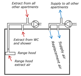
Figure 1. Sketch showing the principle of the test chamber when arranged to represent a dwelling with mechanical supply and exhaust ventilation.
The test chamber pressure was measured using a reference electronic micromanometer with a measurement uncertainty of ±0.3% of the reading plus ±0.3 Pa. The airflow rates were determined by measurement of pressure differentials over co-calibrated dampers. All micromanometers were co-calibrated and differed less than 0.6 Pa at the pressure levels measured in the test chamber, and less than 1.6% of the reading at the levels measured for air flow rate determination. To be able to follow the rapid flow and pressure changes, the readings were recorded typically using a time resolution of 1 value per second.
The dampers for replacement air have different speed of position change. One takes 80 seconds between its end positions, while the other takes 22 seconds. Since the cooker hood's control is instantaneous, using a “flap” damper, there was a short-term pressure drop. In the case of the slower replacement air damper of solution 1, the test chamber pressure dropped towards −25 Pa during less than 1/2 minute. In the case of the faster damper of solution 2, the pressure rarely dropped below −10 Pa.
Figures 2 and 3show examples of measurement results obtained for solution 1, i.e., when the test chamber was arranged to represent a dwelling with mechanical supply and exhaust ventilation. In Figure 2the range hood was inactive (both the range hood damper and the replacement air damper closed). The pressure in the extract and supply air ducts were maintained at 120 Pa and 100 Pa, respectively. The extract airflow rate from WC and shower room was measured to 36 l/s, and the basic extract airflow rate through the range hood was 13 l/s with the damper closed. Thus, the sum of the extract airflows rates was 49 l/s, which was slightly (3 l/s) higher than the supply airflow rate. At this airflow difference the test chamber pressure was −4 Pa.
In Figure 3the range hood was activated, which caused the extract airflow rate through the hood to increase to 34 l/s. In this case the total extract airflow rate was 68 l/s. The activated range hood caused the damper for replacement air to open. The replacement supply air flow rate was then measured to 34 l/s and the total supply airflow rate stabilized at 68 l/s. In this case the extract-supply airflow rate difference became too small to be able to be determined by measurement. The pressure in the test chamber briefly reached −24 Pa and then stabilized at −1 Pa.
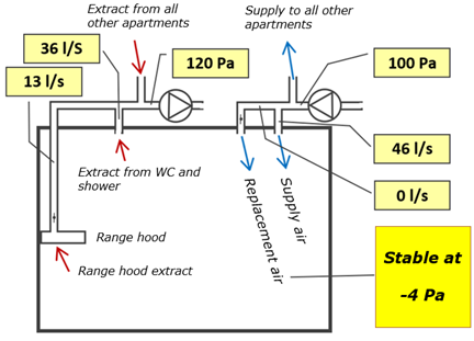
Figure 2. Example of measurement results obtained for solution 1 when the range hood was inactive (with closed dampers). The test chamber was arranged to represent a dwelling with mechanical supply and exhaust ventilation.
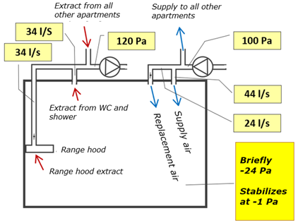
Figure 3.Example of measurement results obtained for solution 1 when the range hood was active (with open dampers). The test chamber was arranged to represent a dwelling with mechanical supply and exhaust ventilation.
The diagram in Figure 4shows an example of the total supply and extract airflow rates monitored together with the room pressure for solution 1. The diagram illustrates how the extract airflow rate increased instantly when the range hood was activated, and the supply airflow rate successively increased as the replacement air damper opened. During this course the room pressure rapidly dropped towards −25 Pa before it was being restored. Later, when the range hood damper was closed, the room pressure became positive for a brief period before the replacement air damper reached its closed position.
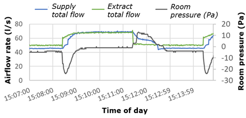
Figure 4. Diagram showing an example of a time series of measurement results obtained for solution 1. The test chamber was arranged to represent a dwelling with mechanical supply and exhaust ventilation.
Figure 5shows an example of measurement results obtained for solution 2 when the range hood was active (with open range hood damper). In this case the test chamber was arranged to represent a dwelling with mechanical exhaust ventilation and air supply through outdoor air vents, e.g., slot devices.
Figures 6 and 7illustrate examples om monitored test data for solution 2.Figure 6shows the measured airflow rates, while Figure 7shows the measured room pressure. When the range hood was activated the room pressure dropped from close to −4 Pa to about −9 Pa. As the replacement air damper opened the room pressure was restored to a value close to −6 Pa.
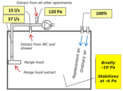
Figure 5. Example of measurement results obtained for solution 2 when the range hood was active (with open damper). The test chamber was arranged to represent a dwelling with mechanical exhaust ventilation and air supply through outdoor air vents, e.g., slot devices.
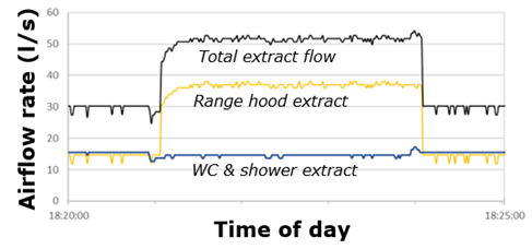
Figure 6. Diagram showing measured airflow rates for solution 2. The test chamber was arranged to represent a dwelling with mechanical exhaust ventilation.
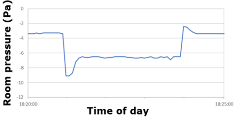
Figure 7. Diagram showing the measured room pressure for solution 2. The test chamber was arranged to represent a dwelling with mechanical exhaust ventilation.
Both solutions met the technology competition requirement regarding limitation of room under-pressure. The solutions are considered robust and long-term stable as they were tested for more than 200 cycles without any malfunction being observed.
Over time, however, dust will accumulate on the dampers, which could affect their functioning; that they get stuck and/or that they do not close tightly in the closed position. However, this has not been tested in the current project. Regular inspection and cleaning will be required, especially of the solution installed as an outdoor air valve/supply air radiator, as the damper in that case is exposed to unfiltered outdoor air. The rather slow change in the damper position contributes to the solutions being judged as robust.
Both solutions have the possibility to add an alarm function with an electric feedback signal in case the damper gets stuck in any position. However, none of the tested solutions had any such function available.
The tests conditions represent modern airtight buildings. In such buildings, very good air flow rate measurement and balancing is required. The air flow balance needs to be restored within 30 seconds. The solutions are ready to be adapted for full-scale tests in apartment buildings.
Ekberg, L. (2023) Tekniktävling - Ventilation i energieffektiva flerbostadshus, Etapp 2: -Utvärdering av system för ersättnings-luft vid spiskåpeforcering, E2B2 Program. The Swedish Energy Agency. https://www.e2b2.se/forskningsprojekt-i-e2b2/varme-och-ventilation/ventilation-i-energieffektiva-flerbostadshus-etapp-2/.
Kempe, P. (2013) Installationssystem i energieffektiva byggnader, SBUF rapport 12541.
Kempe, P. (2014) Artikelserien ”Erfarenheten”, Installationer i energieffektiva byggnader: Del 2 - Luftflödesbalansen viktig i täta byggnader, s.42-44, Energi&Miljö Nr 6-7, 2014; Del 3 - Luftflöden och tryck vid forcering, s.44-46, Energi & Miljö Nr 8, 2014.
Kempe, P. (2017a) Förstudie – Designguide ventilation i energieffektiva flerbostadshus, Version: 1.0. BeBo och Energimyndigheten.
Kempe, P. (2017b) Ersättningsluft vid forcering av spiskåpor/fläktar, Sammanfattning av djupintervjuer och workshop, Version: 1.0. BeBo och Energimyndigheten.
Lstiburek, J.W. (2016) Exhaust-Only Ventilation Does Not Work, ASHRAE Journal, Vol. 58, Issue 8, American Society of Heating, Refrigerating, and Air-Conditioning Engineers, Inc.
Svensk Ventilation (2022) Osuppfångning i spiskåpor och köksfläktar för bostäder ‒ vägledning, Andra utgåvan, Svensk Ventilation.
SS-EN 13141-3:2017, Ventilation for buildings – Performance testing of components / products for residential ventilation – Part 3: Range hoods for residential use without fan, Swedish Standards Institute, SIS.
Follow us on social media accounts to stay up to date with REHVA actualities
0