


Stay Informed
Follow us on social media accounts to stay up to date with REHVA actualities
|
|
|
Abel Sepúlveda | Roman Smirnov | María Dolores Donaire Galiano |
Department of Civil Engineering and Architecture, Tallinn University of TechnologyEmail: absepu@taltech.ee | Department of Civil Engineering and Architecture, Tallinn University of Technology | Department of Architecture, University of Malaga |
In this article, we explain the design process we followed based on a holistic approach to achieve a sustainable, comfortable, and energy-efficient design of a 20-apartment complex called “Vistamadera apartments”. This project was one of the finalists of the Healthy Homes Design Competition 2022 held in CLIMA 2022 international conference on May 2022 [1]. The case study is located at one corner surrounded by nature in Pernis, Rotterdam, a suboptimal urban area for new residential developments because of the surrounding industrial zones (i.e. poor outdoor air quality and high noise levels). The realization of a holistic design was possible thanks to the cooperation between different disciplines: architecture, HVAC engineering, and architectural engineering.
For one side, we tried to avoid north-oriented facades because of the lack of daylight. On the hand, pure west orientations were avoided because of the excess of solar heat gains. Therefore, a symmetrical V-shape building was developed (Figure 1) with NW-SE and NE-SW orientations.
Regarding view contact with the outside, the V-shape building footprint allows (from each apartment) future occupants to keep an eye to the children park (south side) from each apartment and enjoy the view towards the Nieuwe Maas river (north side). The location of the building footprint is not arbitrary: we wanted to split the original buildable plot in three different green areas that could be used for different communal activities: children park in the heart of the plot, street workout park in the NW part of the plot, and a park for elderly people located in the NE part of the plot.
In order to protect the building against flooding events, the whole original plot terrain was elevated 1 m and the first floor of the lower apartments were located in the second floor. In fact, the uncovered first floor of the building allow: (1) occupants have view contact with all the green areas which are populated by transplanted local trees of the limits of the plot; (2) the pass of local wildlife through the plot. The number of parking lots were limited to 10 and 50 bike parking places were located in the first uncovered floor in order to promote healthy and sustainable way of transport.
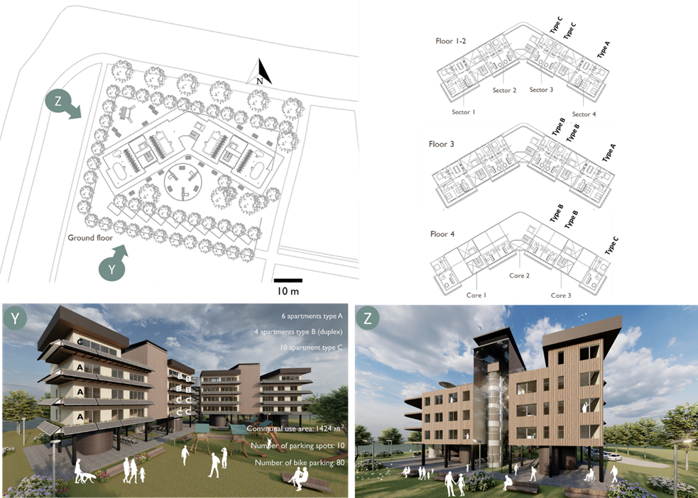
Figure 1. Top view of the plot (upper left figure), top view of the different floors (upper right figure), perspective rendering view from the south-west side of the plot (bottom left figure), and perspective rendering view from the north-west side of the plot (bottom right figure).
Once defined the building volume, the windows were located for each apartment to have at least double orientation. This distribution allows the possibility of use a hybrid ventilation strategy to ensure a good indoor air quality and decrease the overheating risk even in future climatic conditions. For all the rooms, the windows (U-value of 0.6 W/m²K and aluminium frame with U-value of 1 W/m²K) were sized by using novel coupled method based on prediction formulas [2] that allow us to select a suitable combination of g-value (0.3 and 0.4 for south and north orientations, respectively), visible transmittance (Tvis) (60%) and window-to-wall-ratio (WWR) (76-80%) to have enough daylight provision (mean Daylight Factor higher than 2%) and protection against overheating. The size of the windows facing south-east and south-west were increased in order to compensate two design decisions: the high depth and the balconies with PV panels (tittle angle of 45°) of 1 m were installed as passive design solution: they maximize solar heat gains in winter and limit them during summer. Thus, considering a mean urban heat island effect (UHI) between 0.5° and 4° (Figure 2a) [3] and future climatic conditions (year 2085), all the rooms will have at least a 93% of annual comfort hours according to the EN 16798-1:2019 Category II (adaptive comfort criterion) (Figure 2b and 2c). Moreover, the building will have an annual energy consumption of 1.84 51.84 kWh/m² (HVAC), 7.3 kWh/m² (artificial lighting), and 17.52 kWh/m² (occupants’ appliances). Detailed description of the HVAC systems is explained in Step 4.
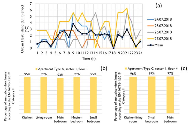
Figure 2. Measured urban heat island effect for different summer days (a) and percentage of annual comfort hours according to the EN 16798-1:2019 Category II for different apartment types: A (b) and C (c).
We selected high quality multi-layer thermal insulation materials for external/interior walls, slabs, and roofs (Figure 3). The combination of these materials was inspired by existing modern Estonian buildings, such as the Narva Study Centre of the Estonian Academy of Security Sciences [4]. The finishing materials for interior and exterior were adapted to the residential use (recyclable paints and vertical cladding wood) and the thickness values for each material were modified according to local Dutch practice (reduction of 50% with respect to the Estonian practice). The results were construction elements with suitable thermal insulation for the Dutch context: U-values about 0.1-0.5 W/m²K for exterior walls/roofs-interior walls/slabs. As secondary criterion, we chose at least one material per layer and construction element with high noise reduction coefficients (NRCs between 0.63-0.9) (green coloured layers in Figure 3). The acoustic comfort performance of all the apartments was satisfactory: the maximum indoor noise level (airborne and contact noise) was below 30 dB when considering different external noise sources simultaneously:
· Contact noise source from upper floor (55 dB)
· Airborne noise source from upper/lower floor (55/55 dB)
· Airborne noise source from ship engine (173 dB)
· Airborne noise sources from traffic and outdoor activities (55 dB)
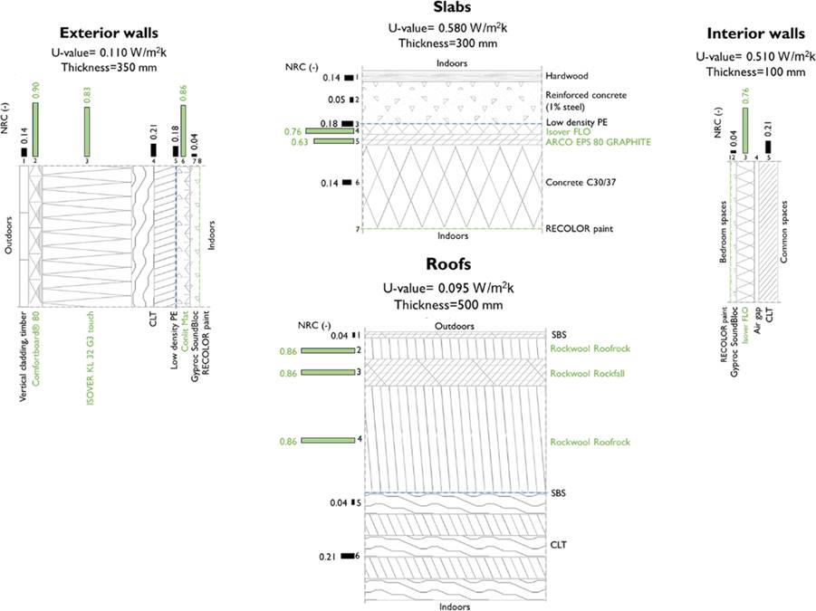
Figure 3. Multi-layer construction elements used, acoustic and thermal properties included.
Thermal comfort, efficiency, and flexibility were considered as main criteria to select the HVAC system. Floor heating (capacity of 54.4 kW) and hot water systems were solved by heat from district heating using heat exchangers (Figure 4). The main heat sources of the local district heating are waste treatment installation (WIP), residual heat, and biomass power plant. Hot water supply temperature must be 55°C, once a day increasing temperature up to 65°C to prevent risk of salmonella disease. Apartments are equipped with hot water circulation to provide hot water inflow maximum in 10 seconds. Floor heating dimensioning temperature for supply and return water is 40°C and 35°C, respectively. The floor heating system was solved with pipe step of 300 mm and 150 mm near external slabs and bathrooms (to improve operative temperature).
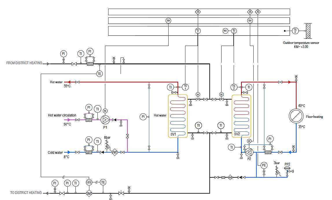
Figure 4. Heating and hot water system.
Apartments cooling was solved with VRV cooling system (Figure 5). Outside unit is located at the roof of the building. Inside units are located at every bedroom and leaving room. Optimal design temperature is set to 25°C. Supply cooling temperature is 7°C and return is 12°C. R410A refrigerant is the working fluid. Cooling and heating simultaneous working must be forbidden by the help of room automation.
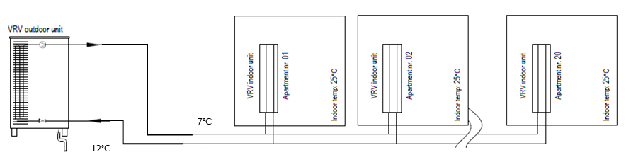
Figure 5. VRV cooling system scheme used for each apartment.
To improve indoor air quality, mechanical ventilation was used (Figure 6). A private ventilation unit was designed per each apartment. Every unit is equipped with particle filters (ePM1 55% (F7) for supply air and ePM10 50% (M5) for exhaust air) to protect indoor spaces against dusted air. Rotor enthalpy type of ventilation heat exchanger was used to return humidity from exhaust air. Thanks to that, it was possible to achieve relative humidity level up to 35% during winter. Airflows of ventilation units were dimensioned according to the restriction of CO₂ level concentration (max 550 ppm above outdoor CO₂ level) and not less than 0.7 ℓ/s·m².
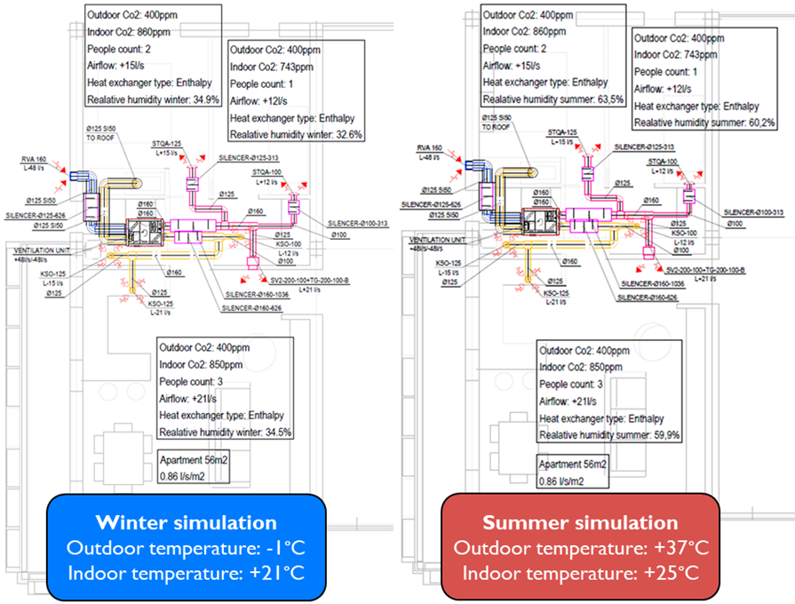
Figure 6. Simulation of the mechanical ventilation system for a critical apartment (type C) under winter and summer climatic conditions.
The on-site energy generation was conducted By the installation of high-efficient PV modules (1.6 × 1,046 m) (total surface of 195 m²) as 45° tilted backwards shading systems of the south-oriented rooms. The PV technology is monocrystalline silicon with a nominal power of 327 W per panel and STC efficiency of 20.07% [5]. There is an inverter per sector, which converts the DC power output of the PV modules to AC power for the occupants’ loads. Each sector circuit is connected to the utility service. Thus, each sector can sell the excess of generated electric energy to the grid. Predicted annual electrical energy demand in kWh/y for each sector can be seen in Table 1. With this system, sectors 1, 2, 3, and 4 could save a maximum of 41.7%, 37.1%, 39%, and 41.7% of the predicted annual electrical energy.
Table 1. Predicted and generated annual electrical energy demand per facade and sector (kWh/y).
Sector ID | Predicted annual electrical energy demand (kWh/y) | Facade orientations | Number of modules per orientation | Generated annual electrical energy demand per facade (kWh/y) | Generated annual electrical energy demand per sector(kWh/y) |
1 | 21480 | SW | SE | 16 | 16 | 4600 | 4360 | 8960 |
2 | 20495 | SE | 28 | 7600 | 7600 |
3 | 20495 | SW | 28 | 8000 | 8000 |
4 | 21480 | SW | SE | 16 | 16 | 4600 | 4360 | 8960 |
We made sure that building occupants have adequate options for personal control over their indoor environment: occupants will have available an integrated smart system to control the indoor environment in terms of visual comfort, thermal comfort, and indoor air quality to different levels: apartment and room level (Figure 7).
Thus, the variables related to visual comfort that can be controlled are the following: covering ratio (i.e. 0= shades in up position, 1=shades totally lowered), intensity of the dimmable artificial lights (0=completely switch off, 1=switch on to maximum brightness), and colour of the light. The variables related to thermal comfort is the traditional indoor set point, which value range depends on the season. Finally, the indoor air quality could be controlled through two variables: openable area ratio (0= windows closed and 1=openable area represents 20% of the window area) and air flow rate generated by mechanical ventilation system (Low=0.7 ℓ/s·m² and Very high= air ventilation rate according to the number of people in the room).
The available control modes at apartment level are: (1) standard mode for occupied/unoccupied apartment (energy efficiency-based criterion, i.e. windows closed and shades lowered) and (2) simulated occupied apartment (security-based criterion considering how occupants normally use the apartment). Finally, there is the possibility to set each of the controlled variables via occupant’s smartphone for rooms such as living room, kitchen, and bedrooms.
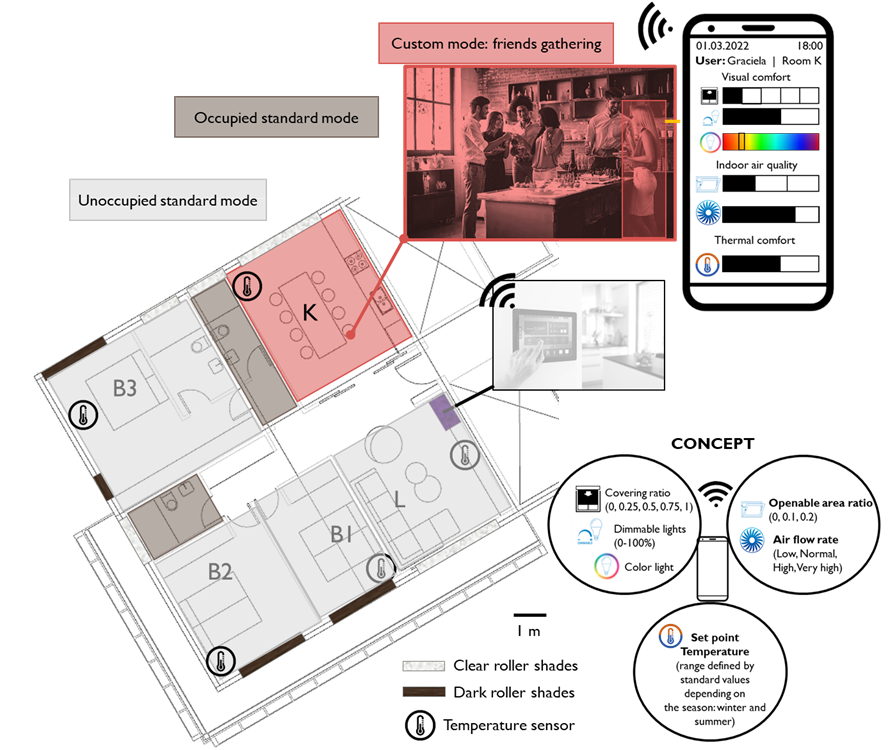
Figure 7. Personal control system concept and example of use.
[1] Winners of the first edition (2022).URL: https://www.healthyhomesdesigncompetition.com/results/2022.
[2] Sepúlveda, A., De Luca, F., & Kurnitski, J. (2022). Daylight and overheating prediction formulas for building design in a cold climate. Journal of Building Engineering, 45, 103532.
[3] Rotterdam Urban Heat Island Explorer (2022). URL: https://doi.org/10.1016/j.jobe.2021.103532.
[4] Narva Study Centre of the Estonian Academy of Security Sciences / 3+1 Architects (2022). URL: https://www.archdaily.com/957698/narva-study-centre-of-the-estonian-academy-of-security-sciences-3-plus-1-architects.
Follow us on social media accounts to stay up to date with REHVA actualities
0