


Stay Informed
Follow us on social media accounts to stay up to date with REHVA actualities

|
|
|
Gongsheng Huang | Nan Zhang | Yuying Liang |
Department of Architecture and Civil Engineering, City University of Hong Kong, Kowloon, Hong Kong | Department of Architecture and Civil Engineering, City University of Hong Kong, Kowloon, Hong Kong | Department of Architecture and Civil Engineering, City University of Hong Kong, Kowloon, Hong Kong |
Radiant cooling has many benefits, such as its high thermal comfort, lower energy use, quiet operation, and smaller equipment footprint, compared with the methods of cooling air of indoor spaces through air circulation [1]. However, radiant cooling applications face great challenges in hot and humid climates from condensation and their limited cooling capacity [2]. In its cooling mechanisms, whether through panel cooling or slab cooling, the radiant surface is also the air-contact surface, as shown in Figure 1(a), where a conventional ceiling radiant-cooling panel (CRCP) is used. In this CRCP, the cooling capacity increases with the decrease of the radiant-cooling surface temperature, but this will increase the risk of condensation. This dilemma has inhibited the commercialization of radiant cooling in hot and humid climates [3], and explains why CRCPs should be used together with other air-cooling systems in practical applications to provide enough cooling for thermal comfort.
Many attempts have therefore been made to solve the condensation problem while increasing the cooling capacity [4]. A typical method is to maintain a low relative humidity so low radiant temperature can be used [5], but this dehumidification is costly and risks degrading the thermal comfort. By realizing that the radiant surface must be isolated from the air-contact surface to essentially solving this dilemma, Morse proposed a radiant-cooling panel covered with a sheet spaced several centimetres from it, filled with dry air, and sealed to prevent room air from contacting the cold radiant-cooling surface [6], referred to as an air-layer-integrated radiant-cooing panel (AiCRCP) and illustrated in Figure 1(b). Thus, the air-contact surface and radiant cooling surface in the AiCRCP are physically separated.
It should be noted that the cover sheet must be transparent to the energy radiated from a body at a temperature range of 29.4°C to 35°C, and thus titled as infrared transparent (IRT) membrane. It enables the panel to act as a radiation heat sink, and heat from occupants in the vicinity can radiate through the transparent cover to the cold plate behind. Teitelbaum et al. [7] revisited this design, investigating several manufactured materials, such as low/high density polyethylene and polypropylene, using Fourier transform infrared (FTIR) spectroscopy to analyse its thermal performance. They also investigated the panel depth (spacing between the radiant-cooling panel and the membrane) to balance radiation, conduction, and convection when AiRCPs was applied to an outdoor environment.
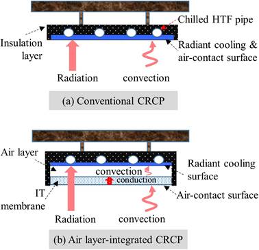
Figure 1. Diagrams of (a) the conventional radiant cooling unit, (b) the air-integrated CRCP.
In our research group, Zhang et al. established a two-flux heat transfer model for the AiCRCP, to analyse the optical, physical and thermal properties of the IR-transparent membrane [8]. Liang et al. investigated the thermal environment and thermal comfort created by an AiCRCP using CFD simulations, and they demonstrated that general thermal comfort indices could be satisfied even when the AiCRCP operated at a very low radiant temperature (e.g. −2.3°C) [9].
Previous literature has demonstrated that the enhanced cooling capacity and reduced condensation risk of AiCRCPs in addition to the thermal comfort they can maintain give them potential applications in hot and humid climates. However, most of the work reviewed above was based on simulation or numerical studies. In this paper, the cooling performance of an AiCRCP prototype and the thermal environment created by the AiCRCP were investigated using experiments, which showed that the AiCRCP could provide higher cooling capacity and better condensation prevention.
The heat transfer process of the AiCRCP is shown in Figure 1(b), where the heat exchange between the AiCRCP and its thermal environment is mainly through two mechanisms. One is radiation that occurs directly between the AiCRCP and its thermal environment; and other is the combination of convection and conduction.
In the first mechanism, since the IRT membrane is assumed to have a poor ability to absorb infrared radiative heat flux and the air-layer is transparent to infrared radiation, the radiative cooling power of the radiant cooling surface will not be much affected by the IRT membrane. In the second mechanism, heat is firstly transferred to the IRT membrane from the air surrounding the AiCRCP through convection, and to the radiant cooling surface through the dry air convection (major) and conduction (minor). It should be noted that the IRT membrane is thin, its internal surface and external surface temperature could be consider as the same in the analysis of the thermal performance of AiCRCP.
Because the air layer has a large thermal resistance to both convection and conduction as shown in the previous work [8], the IRT membrane can be maintained at a high temperature even if the radiant cooling temperature is low, for example 5°C (much lower than 17°C used in conventional CRCPs). Therefore, a low radiant cooling temperature can be used to enhance the cooling capacity of the AiCRCP without increasing the condensation risk.
Currently there is one prototype of AiCRCP in our laboratory with the dimension of 1 m × 1 m. This prototype uses a piece of aluminium plate: on one side high emissivity paint (ε ≈ 0.95) was coated and used as cooling radiant surface, and on another side heat transfer fluid (HTF) pipes were attached and fixed using screws.
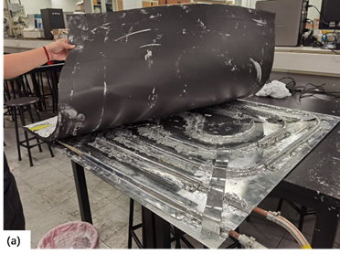
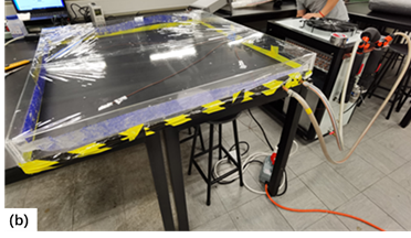
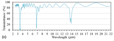
Figure 2. (a) The radiant cooling panel covered by an insulation layer; (b) LDPE membrane covering the panel and sealing a dry air layer; (c) IR spectral transmittance through LDPE membrane using FTIR.
Thermal paste was used to increase the thermal conductivity between the HTF pipe and the aluminium plate, shown in the photo of Figure 2(a). This side was covered with a insulation layer (Nitrile rubber) to prevent cooling loss. A photo of the prototype is given in Figure 2(b). The prototype was connected with an air-cooled chiller that can provide heat transfer fluid with the temperature from −10°C to 20°C with the rated cooling capacity of 5.67 kW and coefficient of performance (COP) of 3.86. A 20 µm thick low-density Polyethylene (LDPE) was used as the IR-transparent membrane to seal a dry-air layer to separate the air-contact and radiant-cooling surfaces. The membrane has a good IR transparency property as shown in Figure 2(c), where the spectral transmittance was measured using FTIR (Spectrum Two, PerkinElmer).
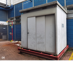
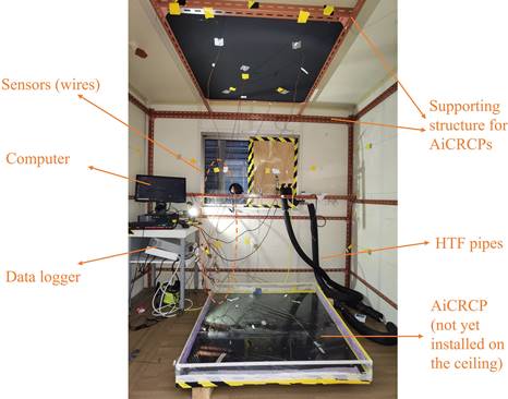
The thermal chamber is placed on a movable structure as shown in the photo of Figure 3(a). Figure 3(b) shows the internal view of the chamber.
a) |
|
| |
b) | |
Figure 3. (a) an external view of the thermal chamber and (b) an internal view of the chamber. | |
A number of sensors/flow meters were installed to measure the temperature, flow and humidity. The measured qualities, number of sensors and sensor uncertainty were summarized in Table 1.
Table 1. Measured quantities, number and uncertainty of sensors.
Measured Quantity | Sensor | Number | Uncertainty |
HTF Fluid temperature | T-type Thermocouple | 2 | ±0.5°C |
Surface temperature | T-type Thermocouple | 18 | ±0.5°C |
Dry bulb air temperature | Swema 03+ | 1 | ±0.1°C |
Indoor air velocity | Swema 03+ | 1 | ±0.04m/s |
Relative humidity | Swema HC2A-S | 1 | ±0.8%RH |
Globe temperature | Swema 05 | 1 | ±0.1°C |
HTF flow rate | Turbine pulse flowmeter | 2 | ±0.5% |
Infrared temperature | FLIR infrared camera | 1 | ±4% |
During the experiment, the thermal chamber was moved into a conditioned large hall, where the space temperature and humidity was maintained to be relatively stable. Inside the thermal chamber, the cooling panel was installed horizontally on the ceiling, facing downward and working as ceiling cooling. In the test, the controlled variables were the indoor air temperature inside the thermal chamber and the radiant cooling temperature of the AiCRCP.
There were three testing scenarios, defined according to the total power of the heaters. In scenario 1, the total power of the heater was the highest; while it was the lowest in scenario 2. In each scenario, the HTF supply temperature was varied in the range of −5~15°C, and the cooling panel radiant surface temperature had a gradient change between 1°C and 19°C. The RH of the indoor air temperature was controlled at 3 levels, i.e. 70%, 60% and 50%. When any variable was changed, the temperatures were measured 20 min after stability. No mechanical ventilation was used during the experiment.
The temperature of the IRT membrane surface (toward indoor air side) is an important variable that indicates the capability of the AiCRCP for condensation prevention. Please note that it is required at least 1°C higher than the dew point of indoor air to avoid condensation risk [1]. The average temperature of the IRT membrane under different radiant cooling panel temperature and different indoor air temperature and humidity were measured.
When RH was maintained at 70%, the cooling panel temperature should be higher than 13.5°C, 8.5°C and 3°C when the indoor air temperature was 28.9°C, 25°C and 19.4°C, respectively. However, when RH=60%, the cooling panel temperature should be higher than 6°C when the environmental temperature was 29°C. When the indoor air was lower than 25°C, the condensation would not occur on the membrane even if the cooling surface temperature was reduced to below 2°C. When RH=50%, the results showed that no condensation occurred on the membrane in these three different indoor air temperatures even the cooling panel temperature was reduced to 1°C.
To further analyse the capability of the condensation prevention of the AiCRCP, the minimum allowable cooling panel temperature allowed was defined, which was the minimal temperature of the panel that can guarantee the IRT membrane temperature being 1°C higher than the dew point of the indoor air. The differences between the minimum allowable cooling panel temperature of the AiCRCP and the conventional ceiling radiant cooling panel were shown in Figure 4 when RH=70% and RH=60%. When RH=70% the minimum allowable temperature of the AiCRCP was around 10.8°C lower than the conventional CRCP; and when RH=60%, the value was about 15°C. Therefore, the AiCRCP has a good performance in preventing condensation in hot and humid climates with lower radiant temperature.
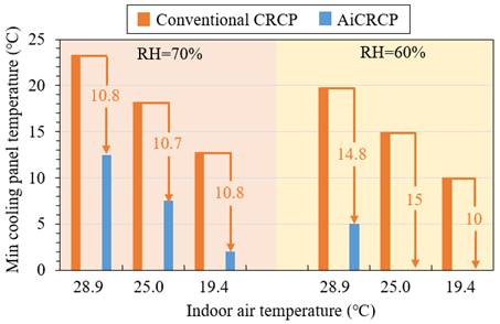
Figure 4. The minimum allowable cooling panel temperature of the AiCRCP and the conventional CRCP.
The cooling capacity of an AiCRCP depends on the thermal environment that is conditioned by the AiCRCP. Here we considered a room with the dimensions of 4 m × 4m × 3m. We assumed that the whole ceiling was used as AiCRCP. The walls and floors had the emissivity of 0.9. Referring to the Figure 2(d), the IRT transmittance of the membrane was assumed to be 80%. The temperature of the room air and the wall/floor surfaces were assumed to be 26°C.
The cooling capacity was the sum of radiative and convective heat fluxes. The cooling capacity of the AiCRCP was compared with that of the conventional CRCP in Figure 5. When the RH was 70%, 60%, and 50%, the dew point temperatures of the room air were 20.12°C, 17.66°C and 14.81°C, respectively. Therefore, the cooling panel temperature of the conventional CRCP were set as 21°C, 19°C and 16°C (approximated 1°C above the dew point). To maintain the IRT membrane temperature at 21°C, 19°C and 16°C, the minimum allowable cooling panel temperatures of the AiCRCP were 13°C, 8°C and 2°C respectively.
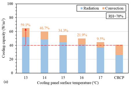
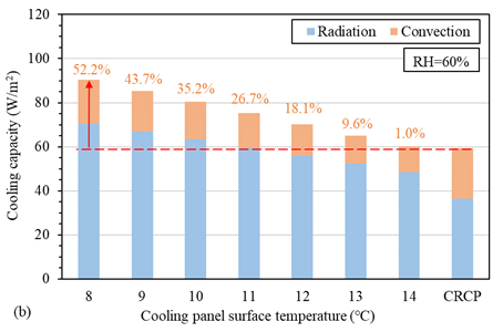
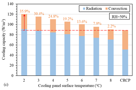
Figure 5. The cooling capacity of the AiCRCP and conventional CRCP.
Figure 5(a) showed the comparison when RH was 70%. The cooling capacity of the conventional CRCP was 40 W/m² using a radiant temperature of 21°C. 7.5% cooling capacity enhancement was achieved by the AiCRCP when its radiant cooling temperature was 17°C. Since the minimum allowable cooling panel temperature of the AiCRCP could be down to 13°C, the maximum cooling capacity of AiCRCP reached 63.63 W/m², improved by 59.1%.
Figure 5(b) showed the comparison when RH was 60%. At this condition, the cooling capacity of the conventional CRCP was 59 W/m² using a radiant temperature of 19°C. Similar cooling capacity was achieved by the AiCRCP when its radiant cooling temperature was 14°C. Since the minimum allowable cooling panel temperature of the AiCRCP could be down to 8°C, the maximum cooling capacity of AiCRCP was improved by 52.2%, reaching 90 W/m².
The comparison when RH was 50% was shown in Figure 5(c), where the cooling capacity of the conventional CRCP was 89 W/m² using a radiant temperature of 16°C. When the radiant cooling temperature of the AiCRCP was 8°C, 2.2% cooling capacity improvement was achieved. Similarly, when we considered the minimum allowable cooling panel temperature of the AiCRCP that could be down to 2°C, the maximum cooling capacity of AiCRCP reached 121 W/m², improved by 35.9%.
Figure 5 also showed that due to a higher air contact surface temperature and a lower radiant surface temperature, the radiative heat flux of the AiCRCP was increased, while the convective flux was decreased when compared to the conventional CRCP. The enhanced radiative heat flux will benefit the heat exchange directly between heating sources (such as occupants) and the cooling panel.
This paper investigated the thermal performance of a prototype of AiCRCP experimentally and then analysed its cooling capacity of AiCRCP in a simple room environment based on the thermal performance of the AiCRCP prototype. The results have shown that
· The AiCRCP has much enhanced capacity to prevent condensation even in hot and humid climates. Due to a large thermal resistance from the sealed air layer, the IRT membrane can be maintained at a high temperature even when the radiant temperature is controlled to a very low temperature.
· Due the possibility of using a low temperature, the cooling capacity of the AiCRCP can be enhanced significantly. At a higher humid environment, for example RH = 70%, the cooling capacity can be improved around 60%.
Thus, the thermal performance of the AiCRCP could make it more preferable when the technique of ceiling radiant cooling is adopted in hot and humid climates.
The research work presented in this paper was supported by a grant from the Research Grants Council of the Hong Kong Special Administrative Region, China (Project No. 11212919).
[1] Rhee K.N., Kim K.W., A 50-year review of basic and applied research in radiant heating and cooling systems for the built environment, Building and Environment 2015; 91: 166-190.
[2] Mumma S.A., Ceiling panel cooling systems, ASHRAE Journal 2001; 43: 28-32.
[3] Zhang L.Z., Niu J.L., Indoor humidity behaviors associated with decoupled cooling in hot and humid climates, Building and Environment 2003; 38: 99-107.
[4] Zhong Z.W., Jiu J.L., Ma W., et al., An experimental study of condensation on an aluminum radiant ceiling panel surface with superhydrophobic treatment, Energy and Buildings 2021; 252: 111393.
[5] Binghooth A.S., Zainal Z.A., Performance of desiccant dehumidification with hydronic radiant cooling system in hot humid climates, Energy and Buildings 2012; 51: 1-5.
[6] Morse R., Radiant cooling. Architect. Sci. Rev. 1963; 6: 50–53.
[7] Teitelbaum E., et al., Revisiting radiant cooling: Condensation-free heat rejection using infrared-transparent enclosures of chilled panels. Architect. Sci. Rev. 2019; 62: 152–159.
[8] Zhang N., Liang Y., Wu H., Xu X., Du K., Shao Z., Zhou X., Huang G.S., Heat transfer modelling and analysis of air-layer integrated radiant cooling unit, Applied Thermal Engineering, 2021; 194: 117086.
[9] Liang Y.Y., Zhang N., Wu H.J., Xu X.H., Du K., Yang J.M., Sun Q., Dong K.J., Huang G.S., Investigation on the thermal comfort of the environment built by decoupled radiant cooling units with low radiant cooling temperatures, Building and Environment 2021; 206: 108342.
Full article: https://proceedings.open.tudelft.nl/clima2022/article/view/395
Follow us on social media accounts to stay up to date with REHVA actualities
0