

Stay Informed
Follow us on social media accounts to stay up to date with REHVA actualities
This article is follow-up part of the article published in REHVA Journal 2018-02 “Natural air conditioning: What are we waiting for?”
|
|
Yamini Patidar | Regina Bokel |
MSc Building Technology,TU Delft | PhD, TU Delft, Faculty of Architecture Dept. AE + T |
The EWF (Bronsema, 2013) is a natural air-conditioning ventilation system which utilizes the environmental energy of earth mass and water through Climate Cascade, wind through Ventec roof and sun through Solar Chimney to air-condition the building in a mainly natural way. The Climate cascade is the heart of the EWF system which utilizes gravity and water for cooling, heating, drying and humidifying the ventilation air. This treated air is supplied to the building. The used air from the building is extracted by a shunt/exhaust shaft which is connected to the solar chimney at the bottom. The Ventec roof is used for creating sufficient pressure for the natural flow of ventilation air.
The system is initially designed for the office buildings in the Western European climate. However, integrating this system in dwellings is complex since the occupants like to regulate their environment and the occupant behaviour greatly affects the performance of the system. In order to investigate the potential of the system for dwellings in terms of its energy-efficiency and thermal comfort potential, a case study building Arthur Van Schendelplein, Delft- is selected. It is a multi-family social housing block consisting of 198 apartments and built in the year 1969.
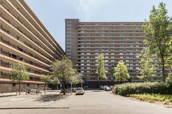
Figure 1. Arthur Van Schendelplein, Delft.
Figure 2 describes the integration of EWF in the design concept. The air enters at the top of the climate cascade and passes through water nozzles which pre-warm or pre-cool the air temperature thereby also humidifying it. During summers, the air is dried and cooled to 18°C. Whereas in winter, air is pre-heated via heat recovery by the twin coil system, after which it is humidified in the cascade and re-heated to 18°C at the foot of the supply shaft. The treated air is finally supplied to the apartments through supply ducts placed at each level of the building. When the pressure generated at the base of the Climate Cascade is less than the pressure loss, auxiliary fans are activated to generate the necessary pressure. For the exhaust, the exhaust ducts from the apartments bring the air to the shunt channel. The air is then pulled up in the Solar chimney due to the effect of thermal draft. The auxiliary fans are activated when the thermal draft is insufficient to pull the air to the top. The Solar Chimney has a heat recovery system at the top to reclaim the heat from the exhaust air before finally exhausting the air from the top of the chimney. The Cascade and the Chimney are both connected through an air to water heat exchanger to an ATES system for restoring the heat from the Chimney during summers and for cooling/heating the water to 13°C before pumping it to the nozzles in the Cascade.
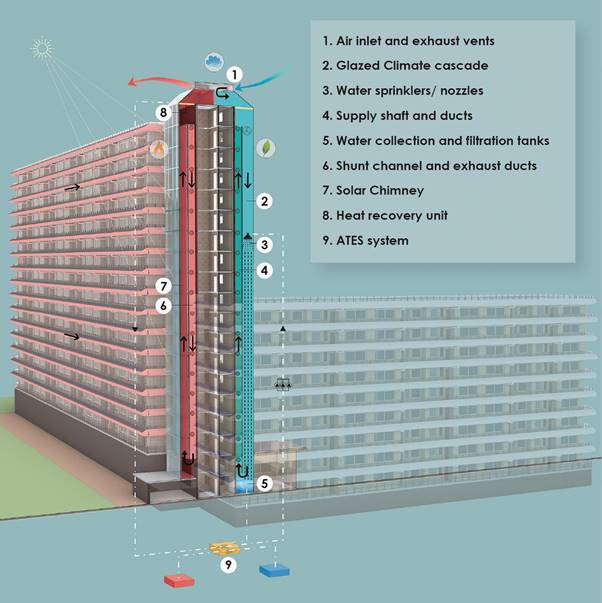
Figure 2. Vertical section through the building showing the integration of the EWF system.
The horizontal supply and exhaust ducts at every floor from the Climate Cascade and Solar Chimney are integrated into the building on the outside of the galleries at opposite sides as shown in Figure 3. The secondary supply ducts to each apartment are provided to living room and bedrooms whereas the secondary exhaust ducts are connected to kitchen, toilet and bathroom.
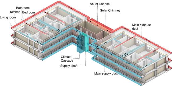
Figure 3. 3d section showing the EWF integration and air flow through the building.
Based on the integrated design concept, design principles are established and the annual energy consumed by the system for its operation is calculated. For a three-bedroom apartment, the minimum fresh air is taken to be 200 m³/h. For the entire building consisting of 198 apartments, the total ventilation rate is thus 39,600 m³/h. The system is designed for demand-controlled ventilation based on an occupancy profile such that the maximum ventilation is provided at night and less during the day for extra energy saving.
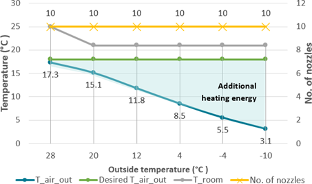
Figure 4. Graph showing the no. of nozzles and air temperature achieved at different outside temperatures.
For the calculated ventilation rate of 39,600 m³/h and an air velocity of 3.5 m/s, a shaft of dimensions 1.7 × 1.7 m is required. The height of the cascade is 54 m.
10 spray nozzles are provided at a height of 36 m instead of the building height of 54 m. The lower placement of the nozzles reduces the pump energy needed to elevate the water till the nozzles.
The air temperature achieved at the base of the Climate Cascade should be close to 18°C after passing through the water of 13°C. During winters, the air temperature at the base is around 10-11°C which needs further heating using a reheating coil at the foot of the supply shaft, see Figure 4.
The pressure loss of the air supply system is estimated as 150 Pa. Using 10 spray nozzles throughout the year, the pressure achieved at the base of the Climate Cascade is less than 150 Pa during the winter months. This results in some amount of fan energy consumption in order to generate sufficient pressure. (See Figure 5)
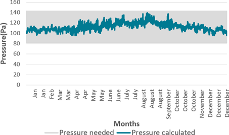
Figure 5. Graph showing the pressure calculated and pressure generated at the base.
For the calculated ventilation rate of 39,600 m³/h and an air velocity of 1 m/s, a shaft of dimensions 1 × 11 m is required. To avoid any daylight hindrance to the apartments, the chimney is placed at the central core behind the staircase.
The pressure loss of the air exhaust system is estimated as 50 Pa. When, the thermal draft generated in the chimney is less than the pressure loss, a fan is needed for the exhaust of the air, see Figure 6.
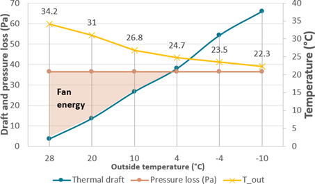
Figure 6. Graph showing the pressure loss and thermal draft generated at different outside temperatures.
The total ventilation energy consumed by EWF system is the summation of the pump energy, heating energy, and fan energy for supply and exhaust. For the case study building this is calculated as roughly 14 kWh/m² which is considerably less than the traditional HVAC systems which consume more than 25 kWh/m².
Having calculated the energy consumption for the EWF system, its effect on the total energy consumption of the building is studied by performing dynamic simulations using the Design Builder software. Since the EWF is a novel ventilation technique, certain simplifications are required to mimic the system in the software. With the goal to assess the effect of EWF on the energy consumption, it is assumed that a constant air temperature of 18°C is supplied in the different rooms.
For achieving the goal of a nearly energy neutral building, integration of EWF in isolation is not a complete solution. Thus, a four-step refurbishment strategy is adopted and calculations for energy and comfort are provided for each stage, see Figure 7.
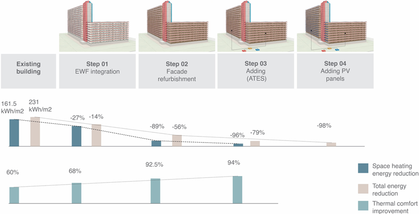
Figure 7. Step-by-step refurbishment strategy with energy savings and comfort performance.
The Climate cascade and Solar chimney are integrated into the building based on the design parameters. Supplying the ventilation air of 18°C through the supply duct reduces the energy consumed for space heating by 27%. The ventilation energy, however, increases for the EWF system since it is a summation of fan, pump and additional heating energy to heat the air till 18°C as compared to the existing case which only has exhaust fans. The total energy consumption of the building with EWF system thus reduces by 14%.
The thermal comfort also greatly improves with a total of 68% hours satisfying the comfort criteria as per the ATG adaptive comfort method. There is a considerable improvement in the summer comfort with EWF ventilation due to the cooling effect of the 18°C air supply With the EWF system, roughly 60 hours exceed the 26°C as compared to the existing building where 95 hours exceed the 26°C comfort criteria.
To achieve the goal of nearly energy neutral refurbishment, the poorly performing parts/system of the building needs to be refurbished. The old Dutch dwellings usually have a poorly insulated building envelope resulting in high heat losses and gains, higher energy consumption and poor thermal comfort. The case study building has a cavity brick wall without insulation, R-value of 0.706 m²K/W and single glazed windows with a U-value of 6 W/m²k. The building envelope thus does not satisfy the present-day Dutch regulations.
For an improvement in the performance, an external insulation layer is added to the building envelope and existing glazing is replaced by double glazing. With a combination of the EWF system with building envelope refurbishment, the space heating load drastically reduces by 89% due to lower heat losses from the renovated building envelope during winter. The total energy consumption reduces by 56%.
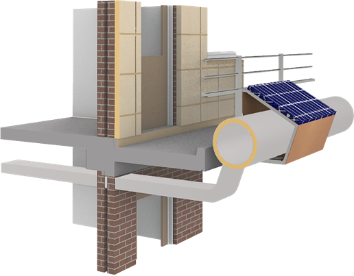
Figure 8. Prefabricated duct cover with solar panel attached to the top.
The thermal comfort shows a big improvement with around 92% of total hours falling inside the comfort criteria.
Adding an ATES system increases the share of renewable energy, getting us a step closer to achieve the goal of nearly energy neutral housing. This also aligns with the Dutch government’s plan to make the Netherlands natural gas-free. Since an ATES system is more energy-efficient than boilers, the total energy consumption is further reduced.
As a part of this step, it is made sure that natural ventilation is possible in summer through operable windows in addition to the EWF system. This improves the summer comfort by reducing the overheating effect caused due to the insulated building envelope.
Solar panels for on-site energy production in combination with the previous three steps, reduces the total energy consumption of the building by 98%. The solar panels are provided as a part of the prefabricated module covering the supply and exhaust ducts attached to the galleries, see Figure 8.
The final refurbished design is evaluated for BENG criteria to derive whether the building achieves the goal of a nearly zero energy building design as shown in Table 1. Since the building satisfies all the three BENG criteria, the refurbishment strategy transforms the building into a nearly zero energy dwelling. The EWF system has an effective contribution in reaching this goal.
Table 1. BENG criteria assessment.
Usable Floor area (UFA)(m²) | 17,820 m² |
|
|
|
BENG category | Requirement (kWh/m².yr) | Formula | Results | |
BENG 1 | < 65 | Total energy need | 57.9 | Satisfied |
BENG 2 | < 50 | (E_total-Lighting)/UFA | 40.14 | Satisfied |
BENG 3 | > 40 | E_ren/ (E_total + E_ren) | 51.28% | Satisfied |
BENG (A Dutch abbreviation meaning “Nearly Energy Neutral Building”) is an energy performance indicator for nearly energy-neutral construction, and serves as the legal requirement in the Netherlands from January 1, 2021. BENG is a three-step approach for the energy concept. | ||||
− BENG 1 stands for the total energy need of a building in kWh/m²/year | ||||
− BENG 2 stands for the primary non-renewable energy use of a building in kWh/m²/year | ||||
− BENG 3 stands for the share of renewable energy expressed in percentage which is determined by dividing the amount of renewable energy use by the total energy use | ||||
With a promising technology and sensible refurbishment strategy, we as architects and engineers can highly contribute towards the sustainability of the built environment. The refurbishment of the apartments with the EWF system results in a major transformation in the energy and comfort performance as well as the architectural aesthetics of the building. The social housing associations could perceive this as an opportunity to showcase the energy-efficiency of their building renovation by integrating the Climate Cascade and the Solar Chimney components. A refurbishment strategy that improves comfort, reduces energy consumption, adds to architectural aesthetics and contributes towards a sustainable zero-energy built environment; What are we waiting for?
This article summarises the graduation thesis ‘Housing Refurbishment using the Earth, Wind & Fire system: Towards a nearly energy-neutral housing in the Netherlands’ written by Yamini Patidar during her Master studies in Building Technology at TU Delft. The thesis is a result of supervision and guidance by Dr. Ben Bronsema, Dr. Regina Bokel and Dr. Ing. Marcel Bilow.
Bronsema, B. 2013 -TU Delft Repository Earth, Wind & Fire: “Natuurlijke Airconditioning”.
Patidar, Y. 2021- TU Delft Repository Housing Refurbishment using the Earth, Wind & Fire System: Towards a nearly energy-neutral housing in the Netherlands.
Follow us on social media accounts to stay up to date with REHVA actualities
0