
Stay Informed
Follow us on social media accounts to stay up to date with REHVA actualities
|
Mikko Iivonen |
MSc (HVAC tech)Purmo Group LtdREHVA Fellowmikko.iivonen@purmogroup.com |
In the energy-efficient renovation of buildings, the thermal insulation and the airtightness of the building envelope, including windows and exterior doors, are improved to almost meet the requirements of new construction. Building services systems, such as heating, water and ventilation systems, as well as electrical and telecommunications systems, will also be modernized to be more functionally efficient and energy efficient.
When old buildings are renovated, the heating needs of the rooms become significantly smaller. It has been shown that even with old buildings the annual energy consumption can be reduced even to less than 50 kWh/(m²a). It is typical that the ratio of heating needs between different rooms also changes, for example, when additional thermal insulation cannot always be applied uniformly to all rooms. Improved ventilation also often changes the heating demand ratio between rooms. For these reasons, a proper new heating demand calculation must be made for the building to be renovated.
As an example, we look at the situation in a typical low-rise building of the 50s and 60s, where the energy consumption of a building is typically around 200 kWh/(m²a).
The comparison is made up of rooms of similar dimensions on the three floors of the building (Figure 1).
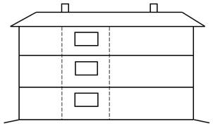
Figure 1. Similar rooms on three overlapping floors.
The calculation of heat demand is based on the instructions in the Energy Efficiency 2018 section of the Finnish Building Code. The starting values for the old building are taken from the appendix to the Ministry of the Environment's Energy Certificate Guide 2018 – typical original design values for existing old buildings.
Note! In the calculation example, a bidirectional ventilation system has been selected as the new ventilation system. Alternatively, the ventilation can be achieved with a unidirectional ventilation system, in which the heat of the exhaust air is transferred to the heating and domestic hot water by means of an exhaust air heat pump. In this case, the old radiators are replaced with supply air radiators. |
Calculation values | Old starting situation | Situation after renovation |
|
Areas, m²: |
|
|
|
· Floor area | 20 | 20 |
|
· Outer wall | 7 | 7 |
|
· Window 2.0x1.5 | 3 | 3 |
|
· Upper, middle and lower sole | 20 | 20 |
|
Room height, m: | 2.5 | 2.5 |
|
|
|
|
|
U-values, W/(m²K): |
|
|
|
· Exterior walls | 0.8 | 0.17 (+15 cm additional insulation) |
|
· Windows and exterior doors | 3.0 | 1.0 |
|
· Upper sole | 0.5 | 0.1 (+25 cm additional insulation) |
|
· Bottom base | 0.5 | 0.5 (no additional insulation, earthy) |
|
|
|
|
|
Ventilation, 1/h: | 0.5 (stack ventilation) | 0.5 (heat recovery η = 80%) |
|
|
|
|
|
Other input data: | |||
· Cold bridges and infiltration of air according to calculation instructions. | |||
· Design temperatures indoor 21°C and outdoor −26°C | |||
| |||
Heat demand, W | Old starting situation | Situation after renovation | Compared to the old |
· 1st floor | 1304 | 429 | 33% |
· 2nd floor | 1119 | 244 | 22% |
· 3rd floor | 1604 | 353 | 22% |
· If the old radiators were kept, the 1st floor (ground floor) room would require 50% higher relative output (33%/22% = 1.50) than the rooms on the other floors. The flow temperature control, the heating curve, is set according to the highest heating demand, i.e. according to the requirements of the 1st floor room. In this case, other rooms receive over-heated water, which leads to the continuous open-close operation of the thermostats, the fluctuation of the room temperatures and the imbalance of the heating network.
· In terms of energy efficiency, and especially when using a heat pump for heat production, it is recommended to replace the undersized 1st floor radiator with ones that are 50% bigger and thus more efficient, so that the flow temperature can be controlled at a lower heating curve level and uniformly for all radiators.
The heating network should be re-dimensioned, and the system valves modernized when the building is renovated with the goal of a nearly-zero-energy building level. There are several factors that have changed: heat demand, distribution of heat, temperature levels and water flows, and possibly a new way of heat production. Typically, the risers and transfer pipes are maintained, the static line control valves are replaced with automatic differential pressure regulators according to the new dimensioning, and the radiators are equipped with new pre-set thermostatic valves.
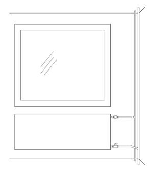
Figure 2. A properly dimensioned radiator has a large heat radiating surface. Radiator replacement is simplified when the connection pipes from the risers to the radiator valves are renewed if possible.
In many cases, old radiators are replaced throughout with new ones. In this way, the design temperatures can be selected optimally for both the heating system and the heat production. All heat sinks in the building can be replaced at the same time which reduces the future replacement needs of individual radiators. This is a macroeconomic solution. The new radiators also enhance the aesthetic look of the rooms.
Recommended radiator network design temperatures:
· Heat pumps 45/35/21°C
· Combustion boilers 55/45/21°C
· District heating 60/30/21°C
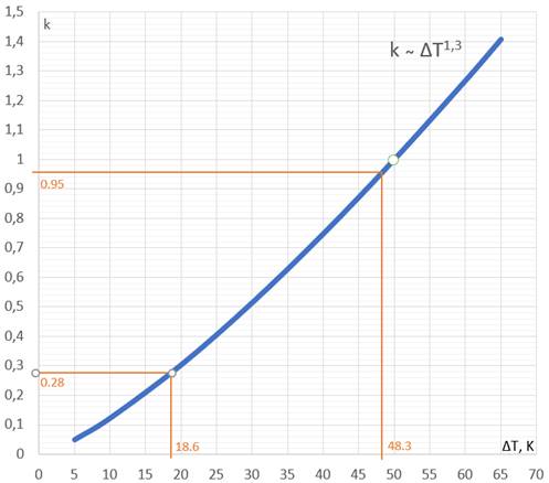
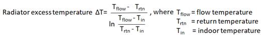
Figure 3. Dependence of radiator output ratio k on excess temperature ΔT. For example, the radiator output at an excess temperature ΔT18.6K (Tflow/Trtn/Tin = 45/35/21°C) can be calculated using a diagram when the radiator output is known at another excess temperature, for example ΔT48.3K (80/60/21°C) the output is 1 000 W. New output is obtained: 1000 W · 0.28/0.95 = 295 W.
The reference value k = 1.0 for ΔT50K in the diagram refers to the heat output capacity of the radiator reported in accordance with EN 442 standard.
The values shown in Figures 3, 4 and 5 can be used for preliminary estimates. However, it is advisable to use more precise output calculation programs published by radiator manufacturers, for example.
| |||||||
Type | 10 | 11 | 20 | 21 | 22 | 30 | 33 |
OP rate | 1.00 | 1.59 | 1.75 | 2.12 | 2.64 | 2.40 | 3.63 |
Figure 4. Output ratios of panel radiators according to radiator type. The type designation describes the number of panels and convection plates. For example, type 21 means that the radiator has two water circulating panels and in addition one convection plate. For example, the output of type 22 is 2.64 / 1.59 = 1.67 times higher than the output of type 11 at the same width / height dimensions. | |||||||
Height | 300 | 400 | 450 | 500 | 600 | 900 |
OP rate | 1.00 | 1.25 | 1.37 | 1.45 | 1.70 | 2.31 |
Figure 5. Output ratios of panel radiators according to height. For example, a 600 mm high radiator of the same type and width is 1.70 / 1.25 = 1.36 times higher than a 400 mm high one. The output of panel radiators is linear in proportion to their width. | ||||||
Follow us on social media accounts to stay up to date with REHVA actualities
0