


Stay Informed
Follow us on social media accounts to stay up to date with REHVA actualities
|
Laurent Socal |
Consultant |
In a context of reduced heating needs due to the increasing level of building insulation, the energy use for domestic hot water has an increasing role. Waste water heat recovery (WWHR in the following) is a technology that allows to cover a significant part of the domestic hot water energy needs with heat recovered from the shower drain.
The analysis of the technology shows the importance of the several factors that determine its efficiency in the daily operation:
· product related properties, like the heat exchanger efficiency as a function of the flow rates;
· installation related properties, like the type of connection of the WWHR device;
· operation properties, like the effects of transients when opening and closing the tap and the set-point temperature of the water heater (for type B and C connections see hereafter).
In the past decades, given the EU climate and building envelope technologies, space heating needs where the dominant factor in determining the energy use of buildings, with values ranging from about 50 kWh/m² year for residential buildings in Mediterranean countries to more than 200 kWh/m² year in cold climates. Currently, there is an ongoing effort to reduce space heating needs by insulating the buildings: the current design target values are in the range 10 to 50 kWh/m² year, depending on climate and building category.
Domestic hot water needs range around 10 to 25 kWh/m²year for the residential sector and they are even much higher for hotels. They should be now under special attention because their relative value in the building energy balance has dramatically increased due to the reduction of energy needs and use for the other comfort services.
Domestic hot water needs do not depend on the building envelope. The possibilities to reduce the non-renewable primary energy use and carbon emissions are limited to:
· keeping a high efficiency of technical systems;
· using renewable and zero carbon energy as a source (renewables);
· and last but not least using heat recovery (recoverable).
An option to reduce the environmental impact of domestic hot water service is recovering heat from the hot water flowing in the drain to the sewer to pre-heat the incoming domestic cold water. Indeed, heat recovery should precede using renewable energy, which should be left only the final touch after having reduced the required output of the generation sub-system.
The basic idea is straightforward: to recover heat from the hot water flowing in the drain to pre-heat the incoming domestic cold water.
Heat recovery requires the simultaneity of the source and destination heat flows, otherwise heat must be stored. Simultaneity is guaranteed natively for showers, which are the main application of waste water heat recovery. Showering is becoming a major use of domestic hot water in buildings: showers are preferred to bathtubs in new houses and in renovations and where bathtubs are installed, they are often used to take showers, too.
There is no simultaneity of draw-off and drain when taking a bath. Some heat recovery is still possible using a heat storage device but it is not the topic of this article which is limited to instantaneous heat recovery.
A WWHR device is a counterflow (sometimes crossflow because of installation constraints) heat exchanger where:
· the drain water of the shower flows through the primary side of the heat exchanger, which is the heating side. The flow through the primary side is normally guaranteed by gravity.
· The domestic cold-water flows through the secondary side of the heat exchanger, which is the heated side. The flow through the secondary side is guaranteed by the pressure of the domestic water distribution network.
The instantaneous type relies on the fact that the primary and secondary flows are simultaneous, except for an initial and final transient due to the water accumulated in the shower basin.
The construction can be vertical or horizontal, as shown in Figure 1.
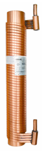
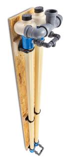
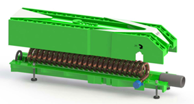
Figure 1. Example of waste water heat recovery exchanger construction, vertical and horizontal type.
The separation between primary and secondary side can be either single or double wall type, according to the required level of tightness, which in turn depends on the risk of contamination and/or uncontrolled losses of water. In case of double wall separation, the space between walls may be filled with an intermediate fluid to promptly identify any loss of tightness. There is ongoing discussion about this topic.
This article deals with:
· instantaneous waste water heat recovery heat exchangers;
· energy efficiency topics.
Functionality and safety requirements like e.g:
· head loss of the secondary side,
· maximum flow rate on both primary and secondary side,
· time constant for cooling,
· level of tightness (single versus double wall),
are assumed to be satisfied for the correct operation of the domestic hot water system.
Basic connection and steady state operation
Figure 2 shows an example of the steady state operating conditions of a basic waste water heat recovery installation on a shower drain using type “A” connection (balanced operation).
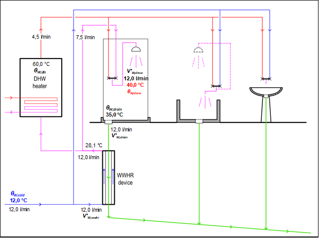
Figure 2. Basic installation – type A connection.
The heat recovery device is installed nearby the shower drain. The device is heating:
· both the cold domestic water feed to the domestic water heater;
· and the cold domestic water to the shower mixer (cold water tap).
A bathtub and a sink are shown in Figure 2 to support the discussion of the possible influence of other devices than showers.
The needs are represented by the 12.0 ℓ/min of domestic hot water flow rate V’W;draw at the draw-off temperature qW,draw = 40°C provided at the shower head. This can be turned into an needed power FW;nd depending on the cold water temperature. The needed power is given by:
| (1) |
where rW and Cw are the density and specific heat of water. The other symbols are shown in Figure 2 and in the preceding text.
With 12°C cold water temperature, the power required to take a shower ΦW;nd is around 24 kW. Assuming a shower duration of 5 minutes, the required volume of water at the tap is 60 litres and the energy need for each shower event is 1.95 kWh.
The recoverable heat
Not all the energy need is recoverable because the water cools down in the shower box and in the drain pipe from the shower outlet to the WWHR device inlet:
· the shower drain temperature qw,drain is assumed to be 35°C, according to an average user behaviour;
· the temperature drop in the connection from the shower drain to WWHR device is assumed to be negligible, unless there is a long connection pipe (several meters).
In principle there is also a loss of mass flow rate in the shower, because of evaporation and/or leaks. This is usually neglected and the flow rate at the drain V’W;drain is assumed to be equal to the draw-off flow rate.
Type A connection guarantees that the flow rates in the WWHR device are balanced (V’W;wwhr = V’W;drain = V’W;draw), so the recoverable power FW;nd;rbl is given by
| (2) |
and the recoverable fraction of needs for type A connection kwwhr,rbl;A is given by:
| (3) |
where all symbols have been already defined.
For the above example, as shown in Figure 2, the recoverable fraction is 82% of needs.
Since the recoverable heat is proportional to the difference between:
· the drain temperature, which is assumed to be constant;
· the cold-water temperature, which depends on the climate
then, the recoverable heat fraction for this configuration (type A connection):
· is not affected by the domestic hot water heater temperature;
· does not depend on the WWHR device efficiency;
· decreases with increased cold-water temperature;
and therefore, WWHR devices are more interesting in cold climates.
A long and uninsulated connection between the shower drain and the WWHR device inlet may cause a further reduction of recoverable heat. Usually, the device is installed next to the shower and this loss is negligible.
The heat exchanger efficiency and the recovered heat
Depending on the heat exchanger design and sizing, not all the recoverable heat will be recovered.
The recovered power during steady state operationFW;nd;rvd;ss is given by:
| (4) |
where
hwwhr is the heat exchanger efficiency.
The heat exchanger efficiency is defined as:
| (5) |
The heat exchanger efficiency can be measured in reference conditions and then interpolated and/or corrected to actual operating conditions. More details are given in the following.
Depending on the heat exchanger design and sizing, only a fraction of the recoverable heat will be recovered. This fraction depends on the heat exchanger efficiency, which may be obtained by a test procedure.
The effect of the presence of other domestic hot water uses
The drains from bathtubs and sinks can also be collected to the WWHR device inlet, as shown in Figure 3. This will obviously increase the amount of recovered heat, especially if the bathtub is used for showers.
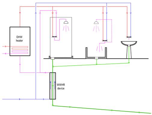
Figure 3. Collecting several drains to a WWHR device.
· at the beginning of showering, the domestic cold water flowing through the WWHR device is not preheated until the warm water from the shower drain reaches the inlet and fills the WWHR device;
· at the end of the showering, the domestic hot water flow is suddenly interrupted and:
o the warm water accumulated in the shower basin will flow through the drain when the incoming cold domestic water flow through the WWHR device is already interrupted and no more heat recovery may happen;
o the preheated water will be trapped in the pipes and will cool down releasing its recovered heat contents in the environment;
o the recovered heat accumulated in the pipe walls and heat exchanger material will be released in the environment as well.
The initial transient does not cause any loss in the heat recovery: as soon as the drain water reaches the WWHR device, there is an established cold domestic hot water flow and heat can be recovered.
The final transient causes the loss of the part of the previously recovered heat:
· contained in the water and pipe materials of the preheated water connections (from the WWHR device outlet to the shower tap and/or to the domestic hot water heater inlet);
· contained in the water accumulated in the shower basin and in the connection from the shower outlet to the WWHR device inlet;
· contained in the WWHR device itself, which includes both its water contents and the heat exchanger material.
The effect of the volume of hot water trapped in the hot water distribution pipe from the water heater to the shower tap is already covered by the final distribution losses.
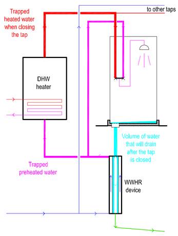
Figure 4. Volumes of water relevant for transient operation.
Transient operation losses also depend on the use pattern. Since transient losses are a given amount of energy for each tapping event, their relative impact will be higher for small tapping events.
As a first approximation, the lost fraction of the recovered heat because of the transient operation kwwhr;use;ls is given by
| (6) |
where:
Vtrans is the equivalent volume of water of the effective total heat capacity that has to cool down at each transient;
Vshow is the volume of water drawn during a single shower event (the product of shower flow rate by the shower duration).
The complement to one of the lost fraction is called the utilisation factor of the WWHR device kwwhr;use and it is the fraction of the recovered heat during steady state operation which is actually recovered.
| (7) |
As an example, with the following assumptions (on the safe side):
· volume of water in the shower box and drain connection: 2 litres (includes all the water from the shower head up to WWHR device inlet);
· volume of preheated water connections (15 m length with inner diameter 14 mm): 2.3 litres;
· volume of water inside the WWHR device (sum of primary and secondary): 2 litres, half to be considered;
· equivalent volume of water with the same heat capacity of the heat exchanger materials: 1 litre, half to be considered;
· total volume of domestic hot water drawn during the shower event: 60 litres (5 minutes @ 12 ℓ/min);
the resulting total equivalent trapped volume is 5.8 litres (2 + 2.3 + 2/2 + 1/2) and the value of the utilisation factor kwwhr;use is 1 − 5.8/60 = 0.90.
Figure 5 shows the “type B connection”, where the WWHR device only preheats the cold domestic water supplied to the shower.
This connection is mainly used when several WWHR devices are connected to a common domestic hot water preparation system.
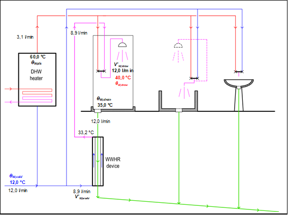
Figure 5. Alternative installation – type B connection.
However, the flow is no more balanced and the maximum recoverable power is given by:
| (8) |
where V’W;wwhr is the flow rate of cold water through the WWHR device, rW and Cw are the density and specific heat of water and the other symbols are shown in Figure 5.
The flow rate through the WWHR device V’W;wwhr depends on the domestic hot water heater set point but also on the efficiency of the WWHR device: the higher the efficiency of the WWHR device, the higher the recoverable heat. The recoverable fraction of needs for type B connection kwwhr;rbl;B is given by:
| (9) |
where (see Figure 5) θW;dis is the domestic hot water temperature in the distribution circuit, equal to the set-point temperature of the domestic hot water heater.
This dependency of the recoverable heat on the WWHR device efficiency may require some iterations in the calculation procedure. As an example, for the given conditions in Figure 5 and with a WWHR device efficiency of 75%, the recoverable heat is 53 % of the domestic hot water needs and the recovered heat 40%. For consistency, the efficiency of the WWHR device has been assumed somewhat higher than in the type A connection due to the reduced flow rate in the domestic water (secondary) side.
The recoverable heat for type B connection:
· increases with higher storage temperature (higher flow rate through the WWHR device to the cold-water connection of the shower);
· increases with higher WWHR device efficiency;
· decreases with higher cold-water temperature.
This makes type B connection more suitable with high temperature heat generators, like boilers, direct electric heaters and CHP.
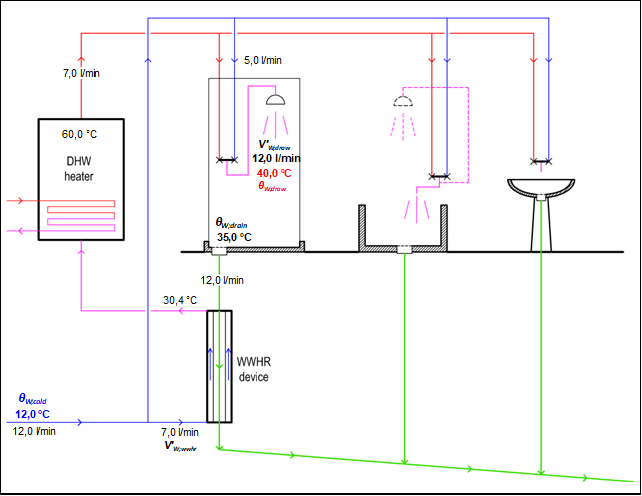
Figure 6. Alternative installation – type C connection.
In case of retrofit, this connection does not require to modify the domestic hot water distribution and is often easily accessible.
However, the flow is no more balanced and the maximum recoverable heat is given by:
| (10) |
Where V’W;wwhr is the flow rate of cold water to the WWHR device, rW and Cw are the density and specific heat of water and the other symbols are shown in Figure 6.
The flow rate through the WWHR device does not depend on the efficiency of the WWHR device. It is given by:
| (11) |
Therefore, the recoverable fraction of needs for type C connection kwwhr;rbl;C is given by:
| (12) |
As an example, for the given conditions in Figure 6, the recoverable heat is 48 % of the domestic hot water needs and the recovered heat 38%.
The recoverable heat for type C connection:
· decreases with higher storage temperature (lower flow rate through the WWHR device);
· does not depend on the WWHR device efficiency;
· decreases with higher cold-water temperature.
The graph in Figure 7 shows the maximum recoverable percentage of needs kwwhr;rbl depending on connection type (A, B and C) and domestic hot water heater set-point (40°C to 60°C) with the following assumptions:
· draw off temperature 40°C;
· shower drain temperature 35°C;
· cold water temperature 12°C.
For type B connection, the recoverable part of needs also depends on the WWHR device efficiency, therefore the graph includes the curves for efficiency 25, 50, 75 and 100%.
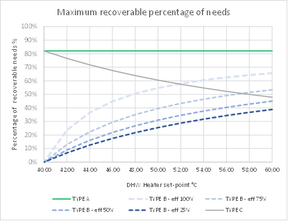
Figure 7. Recoverable fraction of domestic hot water needs kwwhr;rbl.
The impact of the connection type is evident but also that of the domestic hot water heater set-point. A lower set-point (than 60°C) is beneficial for the recoverable heat of type C connection whilst it can seriously reduce the recoverable heat with type B connection.
If there are several showers, using type A connection:
· either the drains are collected to a unique common WWHR device, suitably sized for the maximum simultaneous drain flow rate (similar to what is shown in Figure 3 but all showers);
· or, if multiple heat recovery devices are required to serve several showers, the devices should be connected in series on the cold-water side.
The second option will cause a reduction of the heat recovery efficiency due to additional heat losses of the preheated domestic water flowing through inactive WWHR devices and may also cause a high pressure drop of domestic water.
In both cases a preheated domestic water distribution pipe is required to feed all showers.
Type B connection may be used independently on each one of multiple showers or groups of showers. Each shower (or group of showers) is an independent heat recovery installation
Type C connection requires a series connection of the WWHR devices on the cold-water side, like for type A connection but no change is required in the cold and hot domestic water distribution piping.
If the drains of all devices of a bathroom are collected to the waste water heat recovery of a shower, this may provide some additional domestic hot water heat recovery when warm water is discharged.
This preliminary analysis highlights the influencing factors that should be taken into account in the calculation methods:
· the connection scheme for each WWHR device (de facto standardised as “A” to “C”), which determines the recoverable heat identified as the fraction kwwhr;rbl of needs (see Figure 7);
· the efficiency of the heat recovery device hwwhr, which determines the fraction of recoverable heat which is actually recovered;
· the effect of transient operation, depending on;
o the volume of preheated water and drain water in the pipes, WWHR device and shower basin;
o the use pattern (volume of water for each of tapping event);
which causes the loss of part of the previously recovered energy; this is taken into account by applying the utilisation factor kwwhr;use;
· the effect of multiple WWHR devices connection.
In total the net recovered heat QW;wwhr;rvd is given by:
| (13) |
where the symbols have been defined in the text and kwwhr;rbl;X is the recoverable fraction of needs for connection type X, which may be A, B or C.
It is important to distinguish between:
· the influencing factors depending on product properties, such as WWHR device steady state efficiency, water volume contents during steady state operation and heat capacity of heat exchanger materials;
· versus influencing factors depending on installation choices and use properties, such as the total volume of preheated water connections and the volume of water drawn at each tapping event.
so that product dependent influencing factors can be properly identified by product testing without influence of the test setting properties.
Follow us on social media accounts to stay up to date with REHVA actualities
0