
Stay Informed
Follow us on social media accounts to stay up to date with REHVA actualities
|
Ralf WagnerMember ASHRAE, CTO at LTG Aktiengesellschaft, Stuttgart, Germanywagner@ltg.de |
SymbolsSFP = specific fan power [Ws/m³] q = volume flow rate [m³/h] h = efficiency [–] ht_nrvu = minimum thermal efficiency [–] SubscriptsODA = outdoor air SUP = supply air IDA = indoor air ETA = extract air EHA = exhaust air IAQ = Indoor Air Quality
|
The global efforts made to reduce primary energy consumption are reflected in the many guidelines issued for minimizing the energy consumption of non-residential buildings. In Europe, the Energy Performance of Buildings Directive 2018/844/EU (EPBD) and the Energy Efficiency Directive 2012/27/EU (EED) are now shaping the future, since buildings account for approximately 40 percent of the EU’s energy consumption and 36 percent of CO₂ emissions in Europe. A “high-efficiency air-conditioning system that addresses the issues of healthy indoor climate conditions” must, on the one hand, transport a minimum quantity of outside air into users’ indoor rooms while using as little energy as possible to do so. On the other hand, it must have good heat recovery capabilities in order to minimize the energy used to cover the ventilation heating requirement. Regarding the EU regulation No. 1253/2014, thermal efficiency of the heat recovery system of non-residential ventilation units, ηt_nrvu, has to be 73% at a minimum. This heat recovery system has an air-side pressure loss which cannot be compensated for by natural ventilation. This will make fan-assisted mechanical ventilation indispensable in the future.
In Germany, as of the year 2000, the central ventilation system was substituted by small ventilation units mounted at a constant distance along the façade, which fulfil the same functions as a central ventilation system. Typical restrictions are limited dehumidification, no humidification and limited cooling capacity. The elimination of construction spaces for the high-volume system of ductwork, the reduction of costs for conveying the air and the possibilities of on-demand ventilation are major advantages of decentralized air conditioning. On the other hand, there are large numbers of technical components, such as fans, dampers or filters which need service and maintenance and have been unable to meet the minimum heat recovery requirements, currently placed on non-residential buildings.
Therefore, it is necessary to present a “high-efficiency alternative system”, which is based on the decentralized ventilation concept and overcomes the main drawbacks of known systems. This innovative device concept, which makes use of a transient operating mode, is inspired by the breathing process. During test measurements, it was possible to identify energy consumption levels for air transportation and heat recovery values that have never before been observed at this order of magnitude. During the years 2015-2021, the technology was used in a number of construction undertakings and has proved its functional capabilities and energy efficiency in projects in which nearly 1,000 decentralized ventilation units “breathe” on the building facade in transient mode.
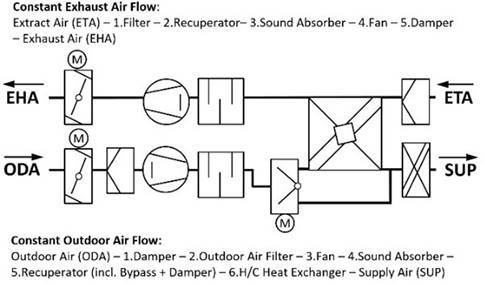
The structures of a decentralized ventilation unit and central ventilation system are very similar. Thus, two openings for outside air and exhaust air are required. These can both be hermetically closed by means of an adjustable motor-driven damper. Two fans provide the ventilation into the room and the exterior. Both must overcome the internal pressure loss of all the device components. Heat recovery is performed by means of a recuperator. When the conventional system construction is transferred to decentralized ventilation units, the external pressure losses are greatly reduced due to the omission of the ducting system in the building, including fire dampers and air diffusers.
|
Figure 1a. Structure of a decentralized ventilation unit with continuous functions: outside air feed, extract air removal, heating, cooling and heat recovery; |
|
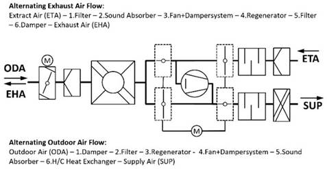
Figure 1b. Structure of a decentralized ventilation unit with transient operating mode and with cyclically alternating functions: outside air feed, extract air removal, heating, cooling and heat recovery. |
In the concept described here (Figure 1b) a single radial fan continuously conveys air, but with double the transient volume flow rate. A damping system consisting of four dampers intermittently switches the airflow direction between outside and exhaust air mode, while the fan’s rotation and transport direction remain unchanged. The bionic transfer of this intermittent ventilation concept from nature has its origins in the breathing process.
The airflow components are arranged in such a way that there is a single airflow path on the “facade side” of the group of dampers. This airflow path contains a single outside air damper, a fine filter, the heat recovery unit and an opening in the facade. This air route is intermittently exposed to outside air (ODA) and exhaust air (EHA). On the “room side” of the group of dampers, there are separate air routes for supply air (SUP) and extract air (ETA).
To avoid pressure differences between adjacent rooms caused by this transient ventilation system, two units can be interconnected simultaneously.
Summing up, this new ventilation system provides many new features: regenerative heat recovery, transient air flow inside the room, calculation of the thermal comfort in transient conditions and the design of the supply air temperature.
The electrical consumption required for transporting the air into and out of the building is a major consideration towards the primary energy requirement of buildings, without reducing the Indoor Air Quality. In the case of a decentralized ventilation unit, this means minimizing the power consumption.
An important fact, as the European standards limit the permitted value for building ventilation in the new-build sector to the class SFP-4. Known decentralized ventilation units with a conventional design with two fans achieve considerably better values, irrespective of the acoustic emissions.
Measurements show that, at a conveyed volume flow rate of 120 m³/h (33.3 l/s), each of the two radial fans has a power consumption of 16 W. The SFPdecentralvalue is therefore SFPdecentral = 480 Ws/m³. Replacing two fans with one fan, that is operated with twice the volume flow rate, namely q=240 m³/h (66.6 l/s), leads to a higher power requirement than in the first approach. In a building, in which the units are operated at an average of 90 m³/h (25 l/s), this means power consumption per fan of < 10 W for each unit. The corresponding SFP value is 194 Ws/m³. To show the resulting energy saving potential for air transport, a comparison of the SFP values is useful. For non-residential buildings, for example, the law in Germany “Gesetz zur Vereinheitlichung des Energieeinsparrechts für Gebäude” (2020) requires a minimum SFP of 1500 Ws/m³ for supply air and 1000 Ws/m³ for exhaust air. The average value of 1250 Ws/m³ can now be compared with the SFP value of the described transient system at an average volume flow of 90 m³/h (25 l/s). The power requirement for the air transport through the building is therefore only 15.52% of the required minimum value. This represents a guaranteed compliance with the European Standards and also a huge energy saving potential for the non-residential buildings sector.
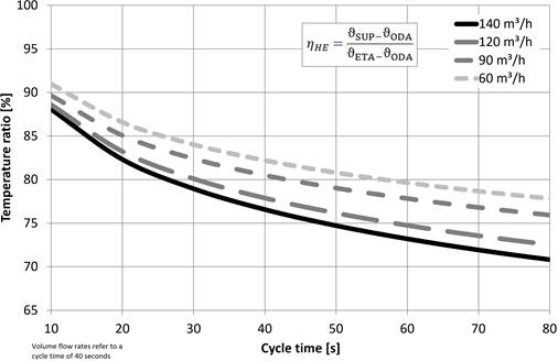
A second aspect in minimizing the primary energy requirement consists in efficient heat recovery. Energy costs can be reduced by minimizing the ventilation heating requirement during the winter. In case of continuous operation, heat recovery is performed using a recuperator. The regenerator acts as a heat store and is alternately loaded and unloaded. Temperature ratios of up to 90% can be reached with this system (Kaup 2009, Mathis 2019).
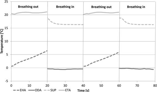
Dimensioning of the switchover heat recovery unit is an optimization process in which heat storage capacity, heat transfer coefficient and thermal diffusivity have to be maximized at a limited volume without increasing pressure loss and the associated acoustic emissions from the fan. Figure 2a shows the air temperatures of a decentralized ventilation unit with integrated regenerator, measured using thermocouples with a very short response time of t90=15 seconds. Each cycle is subdivided into the sub-cycles “breathing in” and “breathing out”. On the “breathing in” sub-cycle, fresh air is conveyed into the room, and on the “breathing out” sub-cycle, used air is conveyed out of it. The diagram shown in Figure 2b makes it clear, that the temperature ratio has to decline as the cycle time increases, because of the average temperature difference between extract air and exhaust air.
|
Figure 2a. Temperature curves in a unit with regenerative heat recovery and a cycle time of 40 seconds; the interval between the extract and exhaust air temperature on “breathing out” and the supply and outside air temperature on “breathing in” is proportional to the amount of heat transferred. |
|
Figure 2b. Temperature ratio in a regeneratively operated heat recovery unit, measured based on DIN EN 308 (1997). The optimum temperature ratio can therefore be set continuously at every operating point. |
For the measurement, recording, judgment and evaluation of thermal comfort the international standards ISO 7726 (1998) and 7730 (2006) are authoritative. Measurements of thermal comfort were conducted in a test chamber with a typical office layout. In this setup, internal heat gains and a temperature-controlled facade were used in order to create steady state conditions for cooling and heating cases.
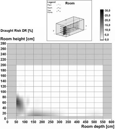
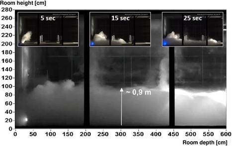
Figure 3a shows the risk of drafts that occurs in the case of floor-level air inflow by means of an underfloor unit. The Figure shows a section through an office room perpendicular to the facade. Even at a distance of 20 cm from the outlet grille, category B of ISO 7730 is complied with. The air is now warmer and forms layers up to a greater height in the room. Instead of a lower pool of fresh air, that is typical for displacement ventilation, a larger volume is now supplied with cool, fresh air. The height of the cooled air volume in the case of a steady state experiment and a supply air volume of 120 m³/h is 0.5 m, for a transient test, the height increases to 0.9 m for cycle times of 40, 60 and 80 seconds. As can be seen in Figure 3b, almost the entire space taken up by a sitting person is covered. As a result, a smaller vertical temperature gradient occurs in the frequented area (Figure 4). This more uniform temperature distribution makes it possible to allow greater room set temperature tolerances in the control system.
|
Figure 3a. Distribution of the local risk of draft; facade at x = 0; risk of draft as per ISO 7730 in the case of cooling; comfort criteria for a sitting person with light summer clothing; humidity = 70%; under-temperature of the supply air compared to the room air = 8 K; cycle time 40 seconds. |
|
Figure 3b. Visualization of the airflow pattern. The height of the cooled air volume is approximately 0.9 m at a supply air under temperature of 8 K, highly inductive supply air after 5, 15 and 25 seconds. |
The cooling capacity that is introduced in a thermally comfortable way into the occupied area increases. An indication for the additional induction is the mixing of the cold supply air with the warm air in a larger volume and therefore the reduction of the temperature gradient (in Figure 4). It is found that, the temperature gradient in the entire frequented area falls off continuously as the length of the period becomes shorter (Figure 4). It can be seen that through the period length factor, the transient operating mode creates an additional degree of freedom for controlling the mixing of the supply air and room air.
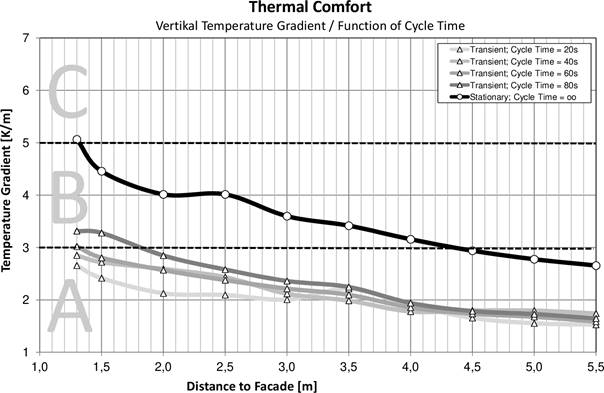
Figure 4. Vertical temperature gradient according to ISO 7730 (1.1 m – 0.1 m) as a function of the cycle time and the distance to the facade and ventilation unit. The volume flow rate is 120 m³/h, the under temperature of the supply air against the extracted air is −6.5K.
For the first "breathing" office building worldwide, 115 decentralized facade ventilation units including the appropriate facade opening were installed.
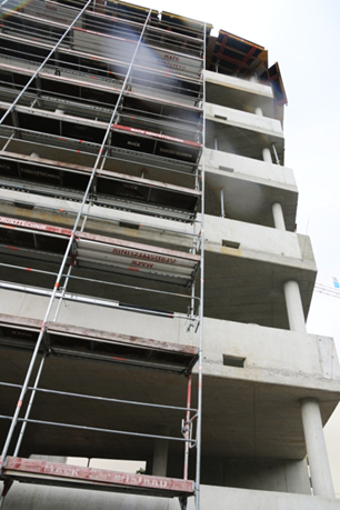
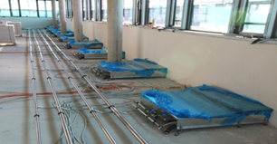
Figure 5. Application of decentralized ventilation unit; Opening in the facade (top). Decentralized devices in the room (bottom).
It has been shown that the ventilation and air conditioning of non-residential buildings using decentralized room-by-room ventilation units offers great potential in terms of reducing the primary energy requirement. A transient operating principle improves energy efficiency by minimizing power consumption for conveying the air and, by using a regenerator, makes it possible to minimize the ventilation heat requirement thanks to the controllable heat recovery with temperature ratios of up to 90%. Thermal comfort in the frequented area is ensured thanks to the high level of inductivity of the supply air jets.
COMMISSION REGULATION (EU) No 1253/2014 of 7 July 2014 implementing Directive 2009/125/EC of the European Parliament and of the Council with regard to ecodesign requirements for ventilation units.
DIRECTIVE (EU) 2018/844 OF THE EUROPEAN PARLIAMENT AND OF THE COUNCIL of 30 May 2018 amending Directive 2010/31/EU on the energy performance of buildings and Directive 2012/27/EU on energy efficiency.
DIRECTIVE 2012/27/EU OF THE EUROPEAN PARLIAMENT AND OF THE COUNCIL of 25 October 2012 on energy efficiency, amending Directives 2009/125/EC and 2010/30/EU and repealing Directives 2004/8/EC and 2006/32/EC.
EN 308. 1997. Heat exchangers - Test procedures for establishing performance of air to air and flue gases heat recovery devices.
Geiger, M. 2013. Beurteilung der thermischen Behaglichkeit bei instationärer Raumluftströmung. Bachelor Thesis, HS Esslingen.
Gesetz zur Vereinheitlichung des Energieeinsparrechts für Gebäude und zur Änderung weiterer Gesetze von 8 August 2020. 2020. Bundesgesetzblatt Jahrgang 2020 Teil I Nr. 37.
ISO 7726. 1998. Ergonomics of the thermal environment - Instruments for measuring physical quantities.
ISO 7730. 2006. Ergonomics of the thermal environment - Analytical determination and interpretation of thermal comfort using calculation of the PMV and PPD indices and local thermal comfort criteria.
Kaup, C. 2009. Raumlüftung mit Hochleistungs-Wärmerückgewinnung. HLH.
Kriegel, M., E. Lichtner, N. Schultz. 2017. Instationäre Quelllüftung. Technische Universität Berlin.
Mathis, P., T. Röder, B. Klein, T. Hartmann, C. Knaus. 2019. EwWalt Study – Energetische Bewertung der dezentralen kontrollierten Wohnraumlüftung in alternierender Betriebsweise. FGK-Report.
Melikov, A. 2010. Thermal Comfort. Local Thermal Discomfort. Lecture held at Czech Technical University in Prague.
Ring, J.W., R. de Dear, A. Melikov. 1993. Human thermal sensation: frequency response to sinusoidal stimuli at the surface of the skin. Energy and Buildings, 20: 159-165.
Follow us on social media accounts to stay up to date with REHVA actualities
0